80
http://www.TYAN.com
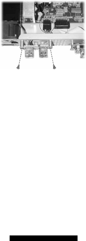
8.5 Replacing the USB Board
The USB board contains the circuitry for the two USB ports located on the system’s
front panel. To replace it, follow these procedures.
1. Remove the cabinet cover (see the previous section in this chapter).
2. Remove the front bezel (see the previous section in this chapter).
3. Remove the two screws securing the USB board to the system chassis and detach
the USB board to pin-header cable from the connector on the motherboard.
Reverse the above sequence when installing the new USB board.
8.6 Replacing the LCD Module
The LCD module contains the system’s LCD screen as well as the six control buttons
located on the front panel. To replace it, follow these procedures.
1. Remove the cabinet cover (see the previous section in this chapter).
2. Remove the front bezel (see the previous section in this chapter).
3. Remove the secondary hard disk drive (see chapter 7 on Adding a Secondary Hard
Disk Drive).
4. Remove the three screws securing the LCD module to the system chassis and detach
the LCD module to pin-header cable from the connector on the motherboard.


