


Installation
Vidikron Vision Model 120 Owner’s Operating Manual 31
PRE
L
IMINAR
Y
3.7
Connections to the Vision
120 and VHD Controller
Proceed as follows to connect the VHD Controller to the Vision 120, your video sources,
external controller(s) – if present – and AC power.
When connecting your equipment:
• Turn off all equipment before making any connections.
• Use the correct signal cables for each source.
• Ensure that the cables are securely connected. Tighten the thumbscrews on connectors
that have them.
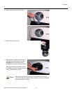
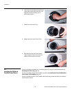
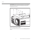
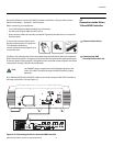
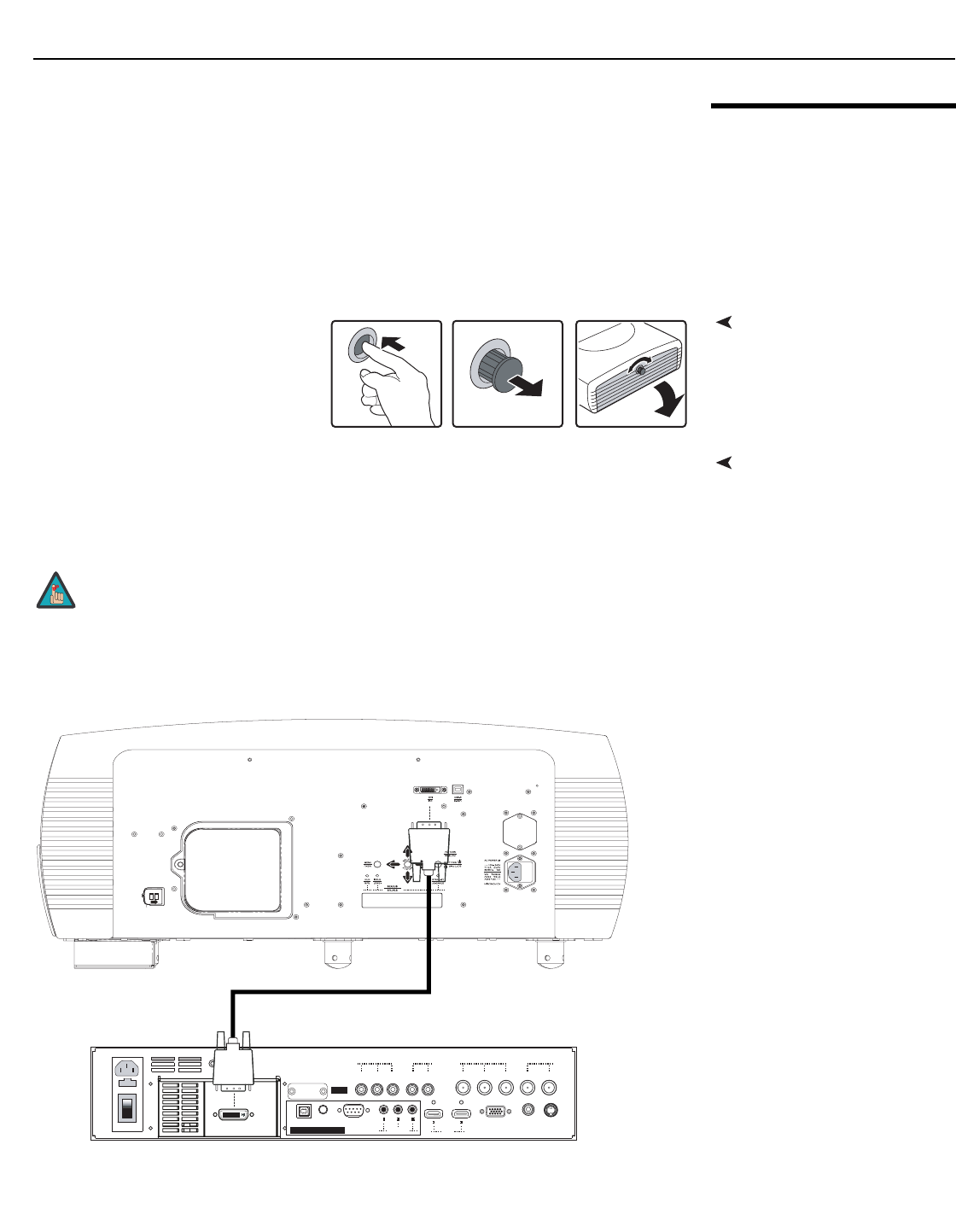
Connector Panel AccessTo access the connector panel, press
the door release button so it pops out.
Turn the knob clockwise or
counter-clockwise and pull gently on it
to open the door.
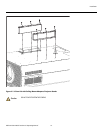
Connecting the VHD
Controller to the Vision 120
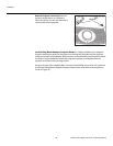
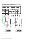
The Vision 120 is designed to receive only digital input signals directly from the companion
VHD Controller/Processor. All signal sources should be connected to the appropriate inputs
on the rear panel of the controller. The signal from the controller is then output to the Vision
120 projector through a DVI-DL (dual-link) cable.
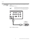
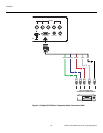
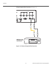
Use a Vidikron DVI Dual-Link (DVI-DL) cable to connect the output of the VHD Controller to
the input of the Vision 120; see Figure 3-7.
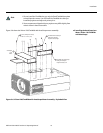
Figure 3-10. Connecting the Vision 120 to the VHD Controller
You CANNOT connect a signal source with DVI output directly to the
Vision 120. It MUST be routed through the VHD Controller for proper
operation.
Note
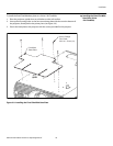
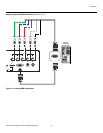
II IIII
TRIGGERS
RS-232 / 485
WIRED
REMOTESERVICE ONLY
SYSTEM CONTROL INTERFACE
HD3 (VGA / Y-Pb-Pr) COMPOSITE S-VIDEO
HD2 (BNC)
VsHs
Pr / RPb / BY / G
HD1 (RCA)
Y / G
VsHs
Pr / RPb / B
HDMI
II I
INPUTS
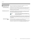
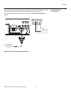
Service port.
Not for user
access
Remove the screw to
pull off the lamp cover.
Remove the screw to
pull off the lamp cover.
L
L
SERVICE PORT
AUTHORIZED
PERSONNEL ONLY