


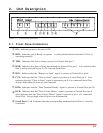
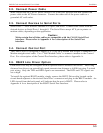
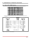
A. Description of System Interfaces
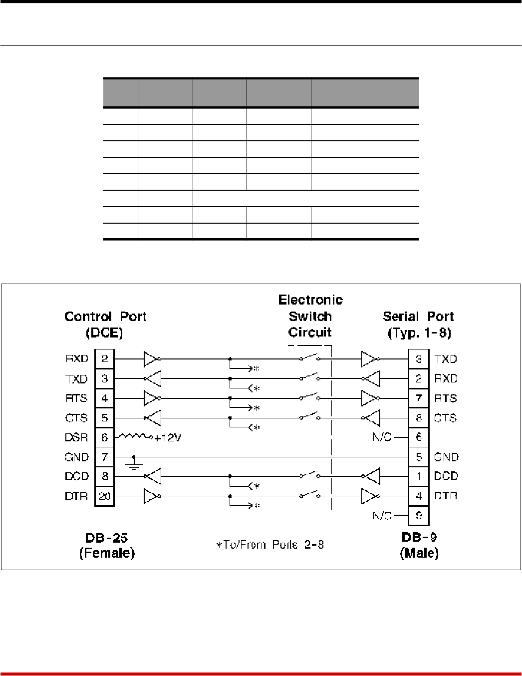
A.1. Control Port (DB25 Female)
The Control Port is a 25 pin female connector wired in a DCE (modem) configuration.
Pin Signal I/O
Not
Connected Connected
2 RXD Input - To Serial Port Pin 3
3 TXD Output Low Follows Serial Port
4 RTS Input - To Serial Port Pin 7
5 CTS Output High * Follows Serial Port
6 DSR Output High Always High
7 GND Signal Ground
8 DCD Output Low * Follows Serial Port
20 DTR Input - To Serial Port Pin 4
* May be forced high by DIP Switches 9 and 10. Always high when all Serial Ports are
connected.
Apx-1
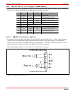
Figure A.1: Control Port / Serial Port Interface