


3.1.4. Auto Connect Serial Port 1 (Switch 7)
When enabled, automatically connects the Control Port to Serial Port 1 on the following
conditions:
1. Power Up
2. After a Timeout disconnect, if selected.
3. After a Code sequence disconnect.
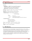
Switch 7 Auto Connect Serial Port 1
Up Enable
Down Disable
3.1.5. Broadcast Mode (Switch 8)
When enabled, permanently activates the Broadcast Mode. Data from the Control Port will be
sent out all eight Serial Ports. Note that when the Broadcast Mode is active, all Serial Port
Status LEDs will be lit.
Data received by the selected Serial Ports will be "ord" and passed out the Control Port. If
data is received by two ports simultaneously, data output may be garbled.
A broadcast one/all jumper located on the circuit board will block received data from Serial
Ports 2 - 8. This feature allows the Control Port to receive a response message from just one
device when broadcasting commands. Receiving data from multiple devices simultaneously
may cause garbled data.
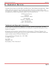
Switch 8 Broadcast Mode
Up Enable
Down Disable
3.1.6. Force CTS (Switch 9)
When enabled, forces the Control Port CTS pin to high.
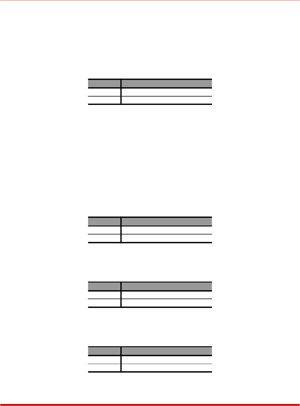
Switch 9 Force CTS High
Down Enable
Up Disable
3.1.7. Force DCD (Switch 10)
When enabled, forces the Control Port DCD pin to high.
Switch 10 Force DCD High
Down Enable
Up Disable
3-2
CAS-81 Code Activated Switch, User's Guide Installation