


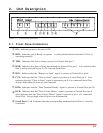
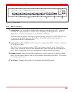
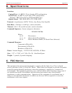
2.2. Back Panel
À
Serial Ports 1 - 8: Eight RS232 DB9 male connectors configured as DTE. Accepts a
standard AT 9 pin to printer or modem cable, depending on the application. Refer to
Appendix A for more information on the Serial Port Interface.
Note that when the RS422 Line Driver Option has been installed, an LED indicator will
be present in the blank above the Serial Port. This LED indicates that the port is
configured for RS422 communication.
Á
Control Port: RS232 DB25 female connector configured for DCE. Accepts a standard
PC to Modem Cable.
The CAS-81 will respond to proper ASCII code strings received by the Control Port.
Once a port is selected, data will pass between the Control Port and the selected Serial
Port. Refer to Appendix A for more information on the Control Port interface.
Â
Default Switch: An 8 position DIP switch that is used to select the Control Port Data
Rate, No-data timeout period, and the Auto connect and broadcast features. This switch
is read upon power up.
Ã
AC Power: Standard AC power cord receptacle and ON/OFF switch.
2-2
CAS-81 Code Activated Switch, User's Guide Unit Description
Figure 2.2: Back Panel