


A.2. Serial Ports 1 through 8 (DB9 Male)
The Serial Ports are 9 pin male, wired in a DTE configuration similar to that of an A computer.
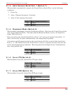
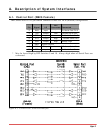
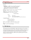
Figure A.1 and the table below describe the Serial Port interface.
Pin Signal I/O
Not
Connected Connected
1 DCD Input - To Control Port Pin 8
2 RXD Input - To Control Port Pin 3
3 TXD Output Low Follows Control Port Pin 2
4 DTR Output Low Follows Control Port Pin 20
5 GND Signal Ground
6 Open
7 RTS Output Low Follows Control Port Pin 4
8 CTS Input - To Control Port Pin 5
9 Open
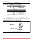
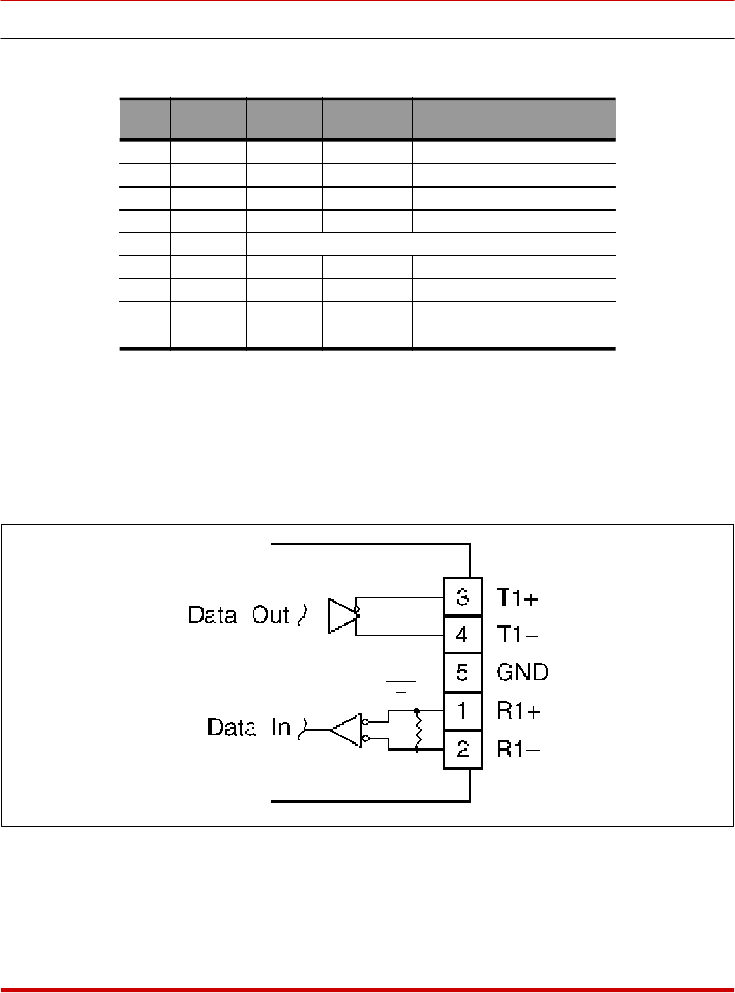
A.2.1. RS422 Line Driver Option
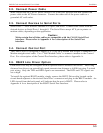
Each Serial Port may be configured with an RS422 balanced line driver. These long distance
line drivers can extend high speed transmission distance to 4,000 feet using 2 twisted pair
wiring. Only the TXD and RXD signals are transmitted. The DCD and CTS signals are set to
high. Figure A.2 below describes the RS422 Serial Port interface.
Note: Handshake signals are not passed. All other pins are open.
Apx-2
CAS-81 Code Activated Switch Appendices
Figure A.2: RS422 Option Interface