


3.2. Connect Power Cable
Make certain that the CAS-81 power switch is set in the OFF position and then connect the
power cable to the AC Power connector. Connect the other end of the power cable to a
grounded AC wall outlet.
3.3. Connect Devices to Serial Ports
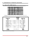
Serial Ports 1 - 8 are wired as standard AT 9 pin COM Ports. Connect data cables from the
desired devices to Serial Ports 1 through 8. The Serial Ports accept AT 9 pin to printer or
modem cables, depending on the application.
Caution:
Make certain that all data cables are compatible with the CAS-81 Serial Port
interface. Please refer to Appendix A for a description of the Serial Port
interface.
3.4. Connect Control Port
The Control Port is configured to appear as a 25 pin DCE modem and accepts a standard PC to
Modem straight wired cable. Use a "Null Modem Cable" to connect a modem to the Control
Port. For a description of the Control Port Interface, please refer to Appendix A.
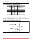
3.5. RS422 Line Driver Option
Each Serial Port may be configured with an optional RS422 balanced line driver. These long
distance line drivers can extend high speed transmission distance to 4,000 feet using 2 twisted
pair wiring. Only the TXD and RXD signals are transmitted. The DCD and CTS signals are
set to high.
To install the optional RS422 module, simply remove the RS232 Driver chip located on the
circuit board adjacent to the desired Serial Port’s connector and plug in the RS422 module. An
LED viewed from the back panel will indicate that the port is RS422. Please refer to
Appendix A for a description of the RS422 Serial Port interface.
3-3
CAS-81 Code Activated Switch, User's Guide Installation