


4-2
IPS-800/1600-D20 Series - User’s Guide
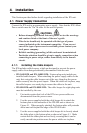
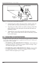
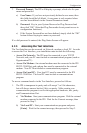
4. Connect the power cables to the power inlets. Check to make sure
that both cables are firmly seated in the power inlet connectors.
5. Align the power cables with the two notches in the top of the slider
plate, and then move the slider plate forward until both cables are
held firmly in place.
6. Tighten the two screws that secure the slider plate to the bottom
plate. Check to make certain that the cables are held firmly in place
by the cable keepers.
4.2. Connection to Switched Outlets
Connect the power cord from your switched device to one of the AC Outlets on
the IPS unit. Note that when power is applied to the IPS, the AC Outlets will
be switched "ON" by default.
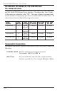
• IPS-800-D20 and IPS-1600-D20 (120 VAC Models): Units include two
separate power busses. Each bus can support a total of 20 Amps. Each
AC Outlet can support up to 15 Amps.
• IPS-800E-D20 and IPS-1600E-D20 (230 VAC Models): Units include
two separate power busses. Each bus can support a total of 20 Amps.
Each AC Outlet can support up to 15 Amps.
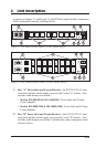
IPS UNIT
POWER INLETS
BOTTOM
PLATE
SLIDER
PLATE
SCREW
RECEPTACLES
Figure 4.1: IPS-800 Series Cable Keeper Installation