


2-1
2. Unit Description
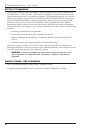
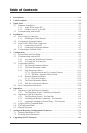
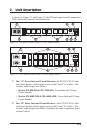
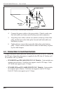
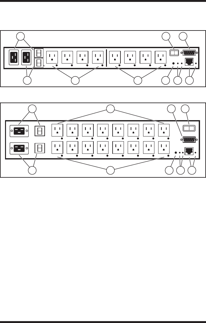
As shown in Figure 2.1 and Figure 2.2, the IPS back panel includes connectors,
LEDs and manual controls described below:
BUS
A
B
A-1 A-2 A-3 A-4 B-5 B-6 B-7 B-8
MAIN POWER
COM
10BaseT
ACT
RDY
ON
DEF
1
2
3
4
5
6
7
8
9
Figure 2.1: IPS-800-D20 Back Panel (120 VAC Model Shown)
➀
Bus "A" Power Inlet and Circuit Breaker: An IEC320-C20 AC inlet
and circuit breaker which supply power to the Circuit "A" outlets. Also
includes cable keeper (not shown.)
• Models IPS-800-D20 & IPS-1600-D20: Power Inlet and 20 Amp
Circuit Breaker.
• Models IPS-800E-D20 & IPS-1600E-D20: Power Inlet and 20 Amp
Circuit Breaker.
➁
Bus "B" Power Inlet and Circuit Breaker: An IEC320-C20 AC inlet
and circuit breaker which supply power to the Circuit "B" outlets. Also
includes cable keeper (not shown.) Includes the same components listed
in Item 1 above.
BUS
A
BUS
B
A-1 A-2 A-3 A-4 A-5 A-6 A-7 A-8
B-9 B-10 B-11 B-12 B-13 B-14 B-15 B-16
MAIN POWER
COM
10BaseT
ACTRDY
ON
DEF
1
2
3
4
5
6
7
8
9
Figure 2.2: IPS-1600-D20 Back Panel (120 VAC Model Shown)