


Á
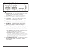
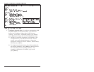
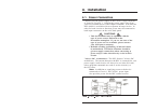
Options Switch: Four DIP Switches which set the default
baud rate, boot delay, echo mode, and timeout.
Â
Default Button: Used in conjunction with the Reset
Button to reset the unit to defaults (see Section 4.3.)
Ã
Console Port: A Male RS-232, DB9 Connector, DTE
configuration. For connection to a local PC.
Ä
Modem Port: A Male RS-232, DB9 Connector, DTE
configuration. For connection to an external modem.
Å
Reset Button: Used in conjunction with the Default
Button to reset the unit to defaults (see Section 4.3.)
Æ
Circuit Module 1: For connection to your DC power
supply and DC powered device. Each circuit is capable of
switching up to 40 Amps. Note that power for control
functions is also derived from the Circuit 1 input terminal.
A. ON Indicator: Lights when the corresponding Circuit
Module is switched On (switch closed).
B. Emergency Override Breaker: If the circuit is
overloaded, the breaker pops out and opens the circuit.
If necessary the Override Breaker can also be manually
pulled out to open the circuit. To reset the circuit,
press the Override Breaker in.
Ç
Circuit Module 2 (Optional): For connection to a second
DC power supply and DC powered device. Same as
Circuit Module 1.