


4. Installation
4.1. Power Connection
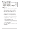
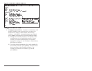
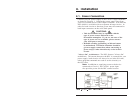
Connect your DC power supply to the Circuit 1 Input Terminals
as shown in Figure 4.1. Connect the power supply lines from
your DC Powered device to the Output Terminals. Note that the
RPC-4840N is available with two separate 40 amp circuits. In
order for both circuits to function, power must be connected to
both input connectors on the unit's back panel.
CAUTIONS:
•
This device should only be operated with the
type of power source indicated on the
instrument nameplate. If you are not sure of the
type of power service available, please contact
your local power company.
•
Reliable earthing (grounding) of this unit must
be maintained. Particular attention should be
given to supply connections when connecting to
power strips, rather than directly to the branch
circuit.
"Always On" Architecture: The RPC features "Always On"
architecture. This means that once the RPC is connected to your
power supply, both circuits will always be set in the ON state,
unless program commands are used to set the circuit(s) to
the OFF state.
Note: In addition to supplying power to the device
connected to Circuit 1, the Circuit 1 power input
also provides power for the RPC control section.