


5. Configuration
5.1. System Mode and User Mode
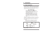
In order to restrict access to sensitive command functions, the
RPC-4840N features two separate operating modes; System
Mode and User Mode.
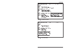
The System Mode allows access to all configuration menus,
command functions and status screens. When the System Mode
is active, Boot/On/Off commands can always be directed to
either of the two switched circuits, even if each circuit has been
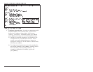
assigned a separate password. The System Mode Status Screen
shows On/Off conditions for both switched circuits, and lists
currently defined system parameters.
The User Mode allows limited access to command functions and
status screens; users are not allowed to access configuration
menus. When the User Mode is active, Boot/On/Off commands
can only be directed to the specific circuit(s) allowed by the User
Password entered at login. If a different User Password is
assigned to each RPC circuit, then a user who accesses the RPC
using the password for Circuit 1 is not allowed to boot or switch
Circuit 2. On the other hand, if the same User Password is
assigned to both circuits, then that user will be able to direct
commands to both circuits. The User Mode Status Screen only
shows conditions at the circuit(s) owned by the User Password;
system parameters are not displayed.
When properly configured, the RPC will display a password
prompt when the unit is contacted via the Console Port, Modem
Port or Network Port. The password entered at this prompt
determines whether the unit will start-up in System Mode or User
Mode. If the System Password (defined via the General
Parameters menu) is entered, the System Mode will be active. If
the User Password (defined via the circuit Configuration Menus)
is entered, the User Mode will be active.
If the System Password is not defined, the RPC will not display
the password prompt, and will always start-up in System Mode.
Once the System Password has been defined, individual users can
be granted access by assigning passwords to the two switched
circuits as described in Section 5.5.