


2. Unit Description
2.1. Front Panel
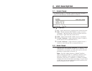
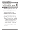
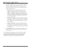
As shown in Figure 2.1, the RPC-4840N front panel includes a
series of LED indicators which function as follows:
À
ON: Lights when Power is applied to the Control Section.
Á
RDY: Flashes when the RPC-4840N is ready to receive
commands. Indicates that the Console Port has received
the "Ready" signal from the control device.
Â
RXD: Lights when the RPC-4840N receives commands.
Ã
Circuit 1 Indicator: Lights when the Circuit 1 Switch is
closed (Power ON to connected device.)
Ä
Circuit 2 Indicator: Lights when the optional Circuit 2
Switch is closed (Power ON to connected device.)
2.2. Back Panel
À
Network Port and Activity Indicator: A 10BaseT, RJ45
Ethernet port for connection to your TCP/IP network. To
communicate via network, you must first specify network
parameters as described in Section 5.6.
Note: The RPC-4840N features a 10BaseT interface.
When connecting the RPC to a 100BaseT interface, note
that most 100BaseT router switches will autosense to
determine if the device is 100BaseT or 10BaseT and then
configure the network interface accordingly. If your router
switch does not autosense, then the network interface port
must be manually set to 10BaseT.