Installation and Configuration
Basic Setup Procedure
Release 2.1 31
Basic Setup Procedure
This procedure can be used as a quick reference for those familiar with the
configuration requirements for the GPIB-M interface as installed in the DC power
supply.
IEEE-488 Controller Connection
Connect the GPIB cable to the supply at connector on the rear panel. Use an
approved IEEE-488 connector and cable when connecting the GPIB Interface to
your IEEE-488 GPIB network. Refer to Figure 2.4, Figure 2.5, Figure 2.6 or
Figure 2.7.
Add a ferrite block to reduce radiated emissions. The one inch square ferrite block
with built-in housing clip is packaged and shipped with the power supply interface
card.
To install the ferrite block:
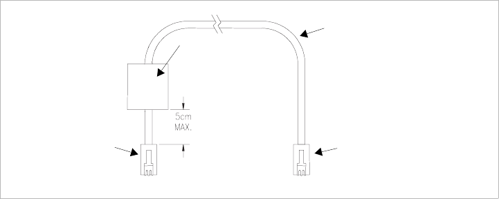
1. Position the block no more than 5 cm (2 in.) from the power supply end of the
user cable.
2. Open the ferrite block housing.
3. Run the cable through the ferrite block. See Figure 2.9, “XFR GPIB Cable with
Ferrite Block” on page 31.
4. Close the housing clip.
The ferrite block ensures that the power supply system meets radiated emission
requirements for CE mark.
Figure 2.9 XFR GPIB Cable with Ferrite Block
GPIB Cable
Ferrite Block
To personal computer GPIB
connector
To po wer supp ly
GPIB connector


