


975-0131-01-01 xv
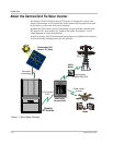
Figure 1-1 Basic System Overview - - - - - - - - - - - - - - - - - - - - - - - - - - - - - - - - - - - - - - - - - - - - 1–2
Figure 1-2 Main Features of the GT Inverter- - - - - - - - - - - - - - - - - - - - - - - - - - - - - - - - - - - - - - 1–4
Figure 1-3 Safety and Data Label Locations - - - - - - - - - - - - - - - - - - - - - - - - - - - - - - - - - - - - - - 1–5
Figure 1-4 Wiring Box for the GT Inverter - - - - - - - - - - - - - - - - - - - - - - - - - - - - - - - - - - - - - - - 1–6
Figure 1-5 Optional Heat Sink Cover and Fan Assembly for the GT Inverter - - - - - - - - - - - - - - - - 1–7
Figure 2-1 Installation Options Overview- - - - - - - - - - - - - - - - - - - - - - - - - - - - - - - - - - - - - - - - 2–3
Figure 2-2 Basic Grounding Overview- - - - - - - - - - - - - - - - - - - - - - - - - - - - - - - - - - - - - - - - - - 2–9
Figure 2-3 Long Distance Grounding Overview - - - - - - - - - - - - - - - - - - - - - - - - - - - - - - - - - - 2–10
Figure 2-4 Grounding With Extra Lightning Protection Overview - - - - - - - - - - - - - - - - - - - - - - 2–11
Figure 2-5 Knockout Locations on Bottom of Wiring Box - - - - - - - - - - - - - - - - - - - - - - - - - - - 2–12
Figure 2-6 Installation Overview- - - - - - - - - - - - - - - - - - - - - - - - - - - - - - - - - - - - - - - - - - - - - 2–15
Figure 2-7 Dimensions of GT Inverter and Knockout Locations- - - - - - - - - - - - - - - - - - - - - - - - 2–17
Figure 2-8 Mounting Bracket and GT Inverter - - - - - - - - - - - - - - - - - - - - - - - - - - - - - - - - - - - 2–18
Figure 2-9 Examples of Mounting on a Pole or Rails - - - - - - - - - - - - - - - - - - - - - - - - - - - - - - - 2–20
Figure 2-10 Installing the Mounting Bracket using Plywood Support - - - - - - - - - - - - - - - - - - - - - 2–21
Figure 2-11 Proper Placement of the Inverter on the Mounting Bracket - - - - - - - - - - - - - - - - - - - 2–22
Figure 2-12 Attaching the fan assembly- - - - - - - - - - - - - - - - - - - - - - - - - - - - - - - - - - - - - - - - - 2–24
Figure 2-13 Location of Fan Connector - - - - - - - - - - - - - - - - - - - - - - - - - - - - - - - - - - - - - - - - - 2–25
Figure 3-1 Removing the Wiring Box Cover- - - - - - - - - - - - - - - - - - - - - - - - - - - - - - - - - - - - - - 3–2
Figure 3-2 AC and DC Terminal Block Location in the Wiring Box- - - - - - - - - - - - - - - - - - - - - - 3–3
Figure 3-3 AC/DC Disconnect Switch Positions - - - - - - - - - - - - - - - - - - - - - - - - - - - - - - - - - - - 3–4
Figure 3-4 DC Connections for Grounded PV Array - - - - - - - - - - - - - - - - - - - - - - - - - - - - - - - - 3–6
Figure 3-5 AC Connections from GT Inverter to Utility Service Panel - - - - - - - - - - - - - - - - - - - - 3–9
Figure 3-6 Parallel GT Inverter DC and AC Wiring - - - - - - - - - - - - - - - - - - - - - - - - - - - - - - - - 3–11
Figure 3-7 Daisy Chain Layout- - - - - - - - - - - - - - - - - - - - - - - - - - - - - - - - - - - - - - - - - - - - - - 3–12
Figure 3-8 Male Network Terminator - - - - - - - - - - - - - - - - - - - - - - - - - - - - - - - - - - - - - - - - - 3–13
Figure 3-9 Xanbus RJ45 Ports in the GT Inverter Wiring Box - - - - - - - - - - - - - - - - - - - - - - - - - 3–13
Figure 3-10 RJ45 Connector - - - - - - - - - - - - - - - - - - - - - - - - - - - - - - - - - - - - - - - - - - - - - - - - 3–14
Figure 3-11 Communications Wiring for GT Inverters in Parallel - - - - - - - - - - - - - - - - - - - - - - - 3–17
Figure 4-1 AC/DC Disconnect Switch Positions - - - - - - - - - - - - - - - - - - - - - - - - - - - - - - - - - - - 4–4
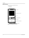
Figure 5-1 Front Panel LCD Location - - - - - - - - - - - - - - - - - - - - - - - - - - - - - - - - - - - - - - - - - - 5–2
Figure 5-2 Location of Status Indicator Lights - - - - - - - - - - - - - - - - - - - - - - - - - - - - - - - - - - - 5–10
Figure 6-1 Location of Fuse, Front Panel Cover Removed - - - - - - - - - - - - - - - - - - - - - - - - - - - - 6–5
Figure 6-2 Inverter and Wiring Box Sections - - - - - - - - - - - - - - - - - - - - - - - - - - - - - - - - - - - - - 6–7
Figure A-1 Output Power vs. Ambient Temperature - - - - - - - - - - - - - - - - - - - - - - - - - - - - - - - - -A–3
Figure A-2 Typical Efficiency- - - - - - - - - - - - - - - - - - - - - - - - - - - - - - - - - - - - - - - - - - - - - - - -A–4
Figures