


Maintenance and Troubleshooting
6–8 975-0131-01-01
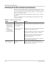
Identifying Error/Fault Conditions and Solutions
Most error or fault conditions will be identified by fault message screens on the
GT Inverter front panel LCD. These are described in the “Fault Mode” section on
page 5–6 of this manual. Most of these fault conditions are self-correcting and
require no user action to remedy.
See “Front Panel Display Screens and What They Mean” on page 5–3 for more
information.
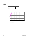
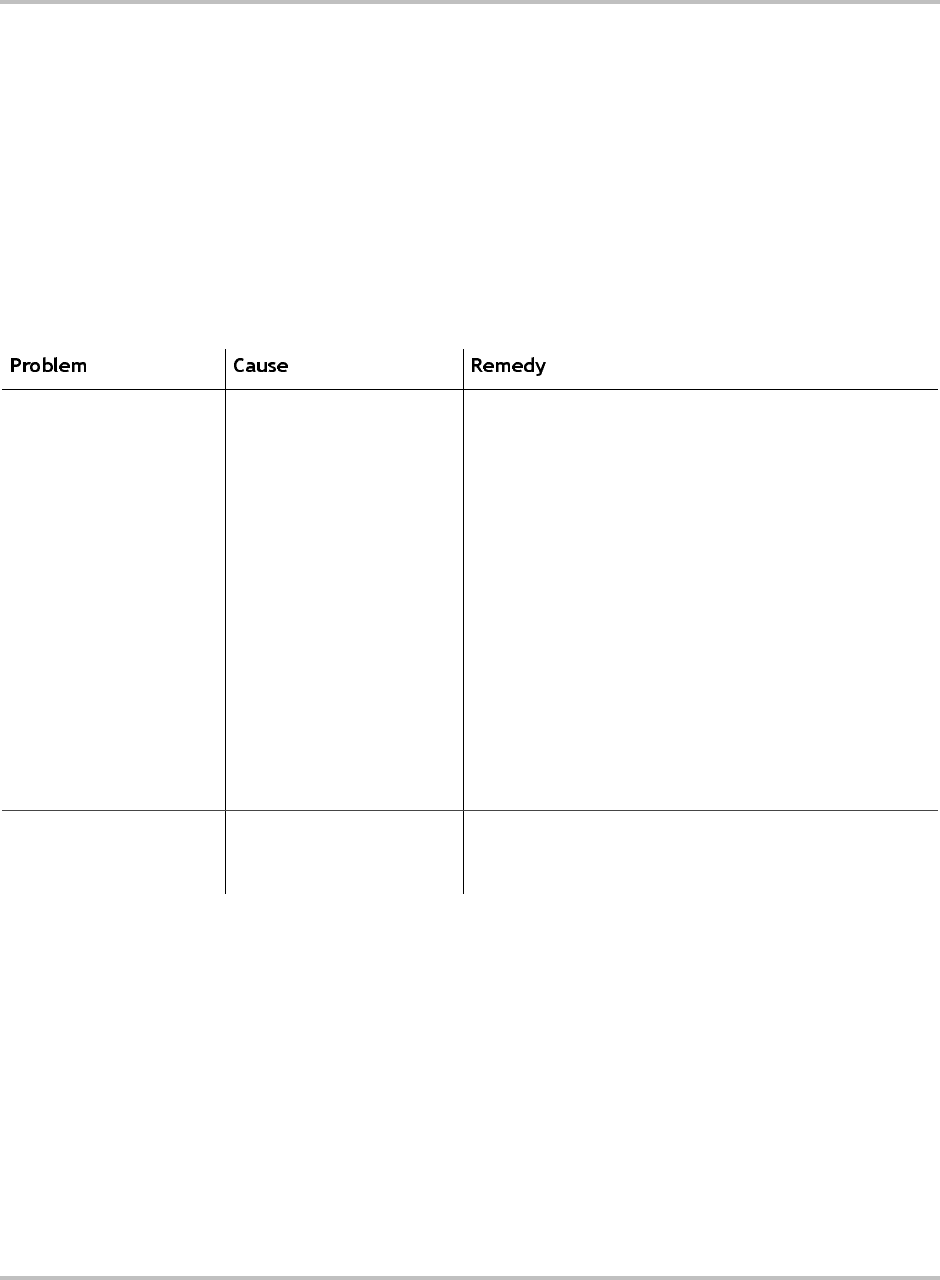
Table 6-1 is intended to assist in determining fault conditions that may require
user action to remedy.
Table 6-1
Troubleshooting the GT Inverter
• The inverter LED
indicator lights do not
illuminate, and the
inverter does not
operate in sufficient
sunlight
• The display reads
“Inverter Offline”
• The Vdc reading is 0.
AC/DC Disconnect Switch
is off, or utilty service
panel AC or DC breakers
are switched off.
No AC grid or DC array
voltage is present.
Turn on AC/DC Disconnect Switch and breakers in the
sequence described in “Startup Procedure” on page 4–2.
Check source of the AC voltage. Ensure that the inverter
AC/DC Disconnect Switch is set ON.
Check AC connections and ensure AC voltage within the
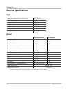
range specified in “Output” on page A–2 is present.
Check DC connections. Check the DC voltage on the
positive and negative input terminalsand ensure
195–550 Vdc is present.
Check for incorrectly wired PV arrays or try again on a
day with brighter sunlight intensity.
Only the inverter RED
LED is illuminated.
Ground fault condition
detected.
Check for any fault messages on the display (see
Table 5-8 on page 5–7). System should be checked by a
qualified electrician and repaired.