


xiii
Figures
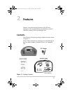
Figure 2-1 Package Contents - - - - - - - - - - - - - - - - - - - - - - - - 2–1
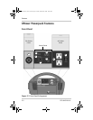
Figure 2-2 Front Panel Enlargement - - - - - - - - - - - - - - - - - - - 2–2
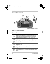
Figure 2-3 Storage Compartment - - - - - - - - - - - - - - - - - - - - - 2–4
Figure 2-4 Back Panel Radio Enlargement - - - - - - - - - - - - - - - 2–5
Figure 2-5 Air Compressor Features - - - - - - - - - - - - - - - - - - - 2–6
Figure 2-6 Emergency Light and Jump-start Port- - - - - - - - - - - 2–7
Figure 2-7 Accessories and Accessory Bag - - - - - - - - - - - - - - 2–8
Figure 3-1 Ventilation- - - - - - - - - - - - - - - - - - - - - - - - - - - - - 3–2
Figure 3-2 Charging with AC Power - - - - - - - - - - - - - - - - - - - 3–5
Figure 3-3 Charging with DC Power - - - - - - - - - - - - - - - - - - - 3–7
Figure 3-4 Charging with a Solar Panel - - - - - - - - - - - - - - - - - 3–9
Figure 3-5 Checking the State-of-Charge - - - - - - - - - - - - - - - -3–10
Figure 3-6 Operating AC Appliances- - - - - - - - - - - - - - - - - - -3–12
Figure 3-7 Operating AC Appliances- - - - - - - - - - - - - - - - - - -3–15
Figure 3-8 Using the Control Panel - - - - - - - - - - - - - - - - - - - -3–16
Figure 3-9 Using the Jump-start Cables - - - - - - - - - - - - - - - - -3–19
Figure 3-10 Emergency Light - - - - - - - - - - - - - - - - - - - - - - - -3–20
Figure 3-11 Using the Emergency Light - - - - - - - - - - - - - - - - -3–21
Figure 3-12 XPower Powerpack Air Compressor - - - - - - - - - - -3–23
Figure 3-13 Value Connector Usage - - - - - - - - - - - - - - - - - - - -3–23
Figure 3-14 Nozzle Adapter Usage - - - - - - - - - - - - - - - - - - - - -3–24
Figure 3-15 Inflating tires - - - - - - - - - - - - - - - - - - - - - - - - - - -3–26
Figure 3-16 Inflating Small Sports Equipment - - - - - - - - - - - - -3–27
Figure 3-17 Radio Features - - - - - - - - - - - - - - - - - - - - - - - - - -3–28
Figure 3-18 Basic Jump-start Cable Safety- - - - - - - - - - - - - - - -3–31
Figure 3-19 Connecting the XPower Powerpack to an External Battery
3–32
Figure 4-1 Accessing the Internal Battery for Replacement- - - - 4–4
Figure 4-2 Replacing the Fuse - - - - - - - - - - - - - - - - - - - - - - - 4–6
975-0162-01-01_Rev-C.book Page xiii Friday, October 20, 2006 10:40 AM