


E-2
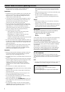
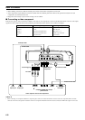
Controls and functions
RS-232C
DVITRIGGER OUT
RGB
/
YPBPR
/
YCBCR
D4 VIDEOINPUT A
INPUT BVIDEOS VIDEO
VDG
/
YR
/
PR
/
CR
HD/SYNC
B
/
PB
/
CB
8
12345 6 7
90 q w
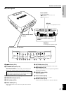
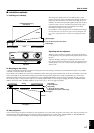
Focus ring, zoom ring
Focuses and zooms the lens
Remote sensor
Lens
Ventilation (exhaust) slot
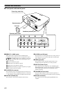
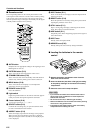
Terminal panel <side>
1—5 INPUT A (BNC jacks)
These jacks receive component video and RGB signals.
Component video signals from an A/V component are sent to
the 1—3 jacks. RGB signals from a computer are sent to the
1—5 jacks. Use a BNC cable when connecting this unit to
another component.
1 G/Y (G or luminance signal)
2 B/PB/CB (B or color-difference signal)
3 R/P
R/CR (R or color-difference signal)
4 HD/SYNC (horizontal sync signal, composite sync signal)
5 VD (vertical synchronous signal)
6 D4 VIDEO (D connector)
This connector receives video signals from the D connector of
an A/V component and is compatible with the D1—D4 format.
* This connector is designed for the Japanese D format only.
7 RS-232C (D-Sub 9-pin)
This connector is used for an examination in the factory.
8 S VIDEO (mini DIN jack)
This jack receives S video signals from the S video jack on an
A/V component. Use an S video cable when connecting this
unit to another component.
9 VIDEO (pin jack)
This terminal is for the composite signal from the video
terminal of the A/V component. Use a video pin cable.
0 INPUT B (D-Sub 15-pin)
This connector receives component video and RGB signals
(RGB/YP
BPR/YCBCR) from an A/V component or a computer.
Use a D-Sub monitor cable when connecting this unit to
another component.
q TRIGGER OUT (mini jack)
This jack outputs signals to control external components. A
potential of +12V will be provided while this unit is projecting.
w DVI (DVI connector)
This connector receives DVI signals (digital RGB) from a
computer.
■ Front panel and terminal panel
Lens cap