


ES-4124 User’s Guide
Chapter 31 VRRP 207
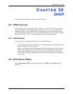
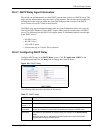
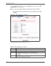
Figure 108 VRRP Status
The following table describes the labels in this screen.
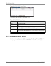
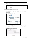
31.3 VRRP Configuration
The following sections describe the different parts of the VRRP Configuration screen.
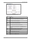
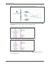
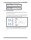
31.3.1 IP Interface Setup
Before configuring VRRP, first create an IP interface (or routing domain) in the IP Setup
screen (see the Section 7.6 on page 75 for more information).
Table 78 VRRP Status
LABEL DESCRIPTION
Index This field displays the index number of a rule.
Network This field displays the IP address and the subnet mask bits of an IP routing domain
that is associated to a virtual router.
VRID This field displays the ID number of the virtual router.
VR Status This field displays the status of the virtual router.
This field is Master indicating that this switch functions as the master router.
This field is Backup indicating that this switch functions as a backup router.
This field displays Init when this switch is initiating the VRRP protocol or when the
Uplink Status field displays Dead.
Uplink Status This field displays the status of the link between this switch and the uplink gateway.
This field is Alive indicating that the link between this switch and the uplink gateway is
up. Otherwise, this field is Dead.
This field displays Probe when this switch is check for the link state.
Poll Interval(s) The text box displays how often (in seconds) this screen refreshes. You may change
the refresh interval by typing a new number in the text box and then clicking Set
Interval.
Stop Click Stop to halt system statistic polling.