


ES-4124 User’s Guide
42 Chapter 3 Hardware Overview
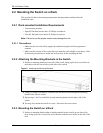
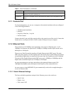
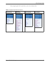
Figure 10 Installed Transceiver
3.1.3.2 Transceiver Removal
Use the following steps to remove a mini GBIC transceiver (SFP module).
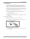
1 Open the transceiver’s latch (latch styles vary).
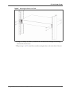
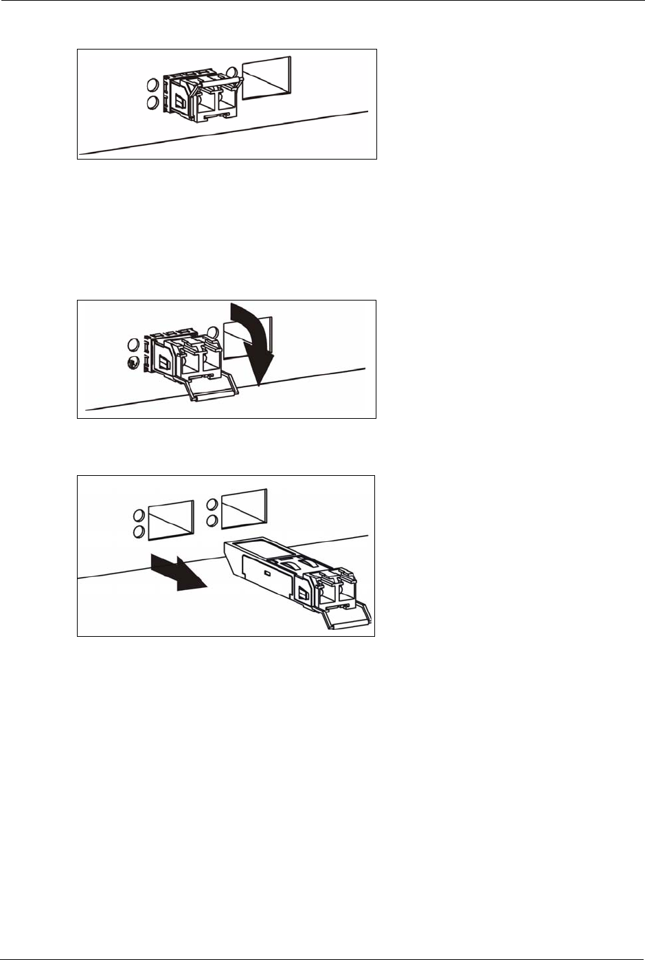
Figure 11 Opening the Transceiver’s Latch Example
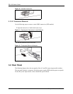
2 Pull the transceiver out of the slot.
Figure 12 Transceiver Removal Example
3.2 Rear Panel
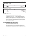
The following figures show the rear panels of the AC and DC power input model switches.
The rear panel contains a connector for backup power supply (BPS) and the power receptacle.
For the DC power input model, it also contains the power switch.