


3-7
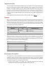
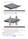
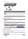
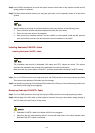
Figure 3-8 Ground through an AC power PE wire
(1) Three-wire AC power input cable (2) Switch rear panel
Use the PGND cable provided with the switch to connect the grounding strip in the equipment room.
Otherwise, the grounding effect may not be ensured, which easily causes damage to the switch.
Connecting the Power Cords
Make sure that the ground wire has been properly connected before powering on the switch.
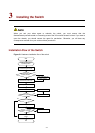
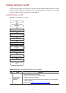
Table 3-1 Power cord connection methods of the Switch 4510G
Switch module Power supply mode Connection method
AC power supply Connecting the AC Power Cord
Switch 4510G 24-Port
Switch 4510G 48-Port
RPS power supply
Connecting the RPS Power Cord
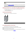
Connecting the AC Power Cord
Step1 Wear an ESD-preventive wrist strap, ensure a good skin contact and make sure that the
ESD-preventive wrist strap is properly grounded.
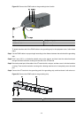
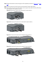
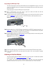
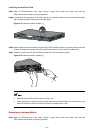
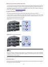
Step2 Install the bail latch to prevent the AC power cord from accidentally falling off. Fix the bail latch into the
holes located at the two sides of the AC power receptacle. Then pull the bail latch upwards (see in
Figure 3-9 or Figure 3-11).
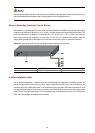
Step3 Connect one end of the AC power cord to the AC receptacle on the switch (see callout 1 in
Figure 3-10
or
Figure 3-12).