


3-12
Installing Switches for an IRF
The Switch 4510G support the IRF function. You can install IRF-capable interface modules to connect
multiple switches through the 10 GE ports to form a logical entity, thus to establish a new intelligent
network with high reliability, expandability and manageability.
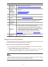
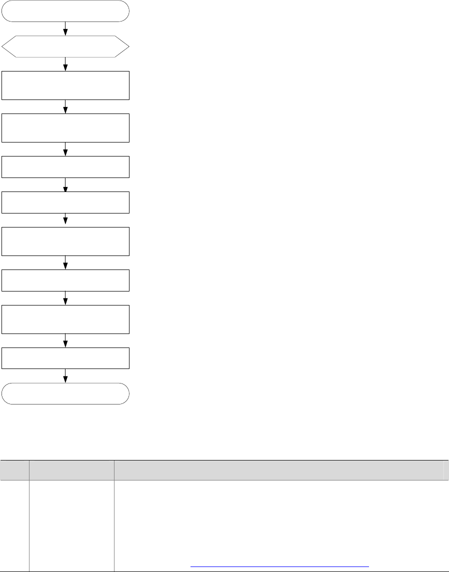
Installation Flow for an IRF
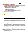
Figure 3-17 Installation flow for an IRF
Connect the PGND cables and
power cords for the switches
Install Interface modules
Configure software for the IRF
members
Power off the switches
Connect cables between every
two switches in the IRF
End
Power on the switches
Power on the switches
Draw a plan for an IRF
of switches
Install switches to the correct
position as per the plan
Start
Table 3-2 Description of the installation flow for an IRF of switches
No Task Remarks
1
Draw a plan for
an IRF with
switches
Take the following into consideration:
z Number of IRF members and the bandwidth
z Interface modules and cables
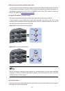
z Physical connection mode( daisy chain connection or ring connection)
z Cable connection
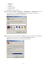
For details, see
Drawing a Plan for an IRF with Switches.