


3-10
Installing an Interface Card
Step1 Wear an ESD-preventive wrist strap, ensure a good skin contact and make sure that the
ESD-preventive wrist strap is properly grounded.
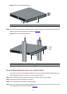
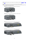
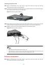
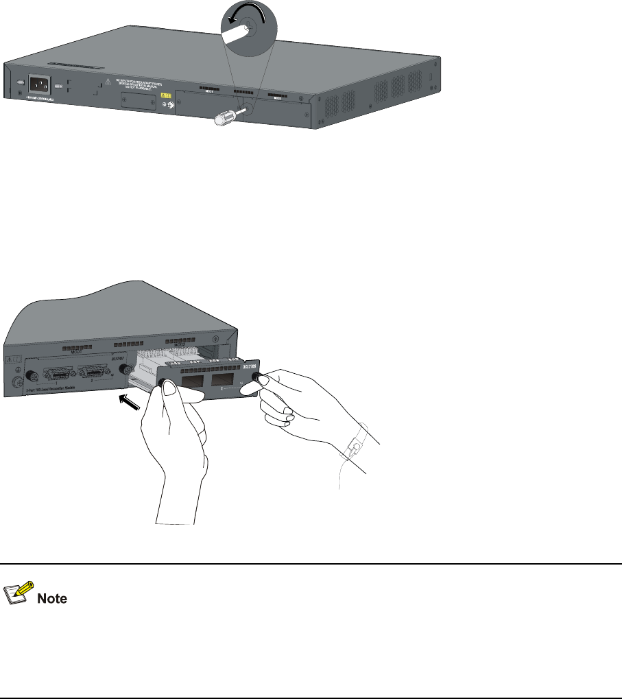
Step2 Loosen the mounting screws of the filler panel on the interface module slot of the switch's rear panel
with a Phillips screwdriver and remove the filler panel.
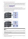
Figure 3-15 Install an interface module (1)
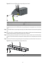
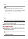
Step3 Hold the fastening screws on the front panel of the XFP interface module, and gently push the interface
module in along the slot guide rail until the interface module is in close contact with the switch.
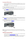
Step4 Tighten the captive screws with a Phillips screwdriver to fix the interface module.
Figure 3-16 Install an interface module (2)
z Keep the removed filler panel properly for future use.
z When tightening the fastening screws at both sides of the optional module with a screwdriver or an
electric screwdriver, make sure that the torque is not bigger than 0.4 N-m.
Removing an Interface Module
Step1 Wear an ESD-preventive wrist strap, ensure a good skin contact and make sure that the
ESD-preventive wrist strap is properly grounded.