


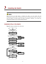
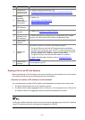
3-9
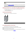
Connecting the RPS Power Cord
The Switch 4510G 24-Port and Switch 4510G 48-Port can work with RPS500-A3 using its +12 V/10.5 A
output and a 0404A03C power cord. Procedures for connecting the RPS power cords are the same for
these three models.
Follow these steps to connect an RPS power cord to the switch:
Step1 Wear an ESD-preventive wrist strap, ensure a good skin contact and make sure that the
ESD-preventive wrist strap is properly grounded.
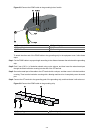
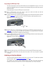
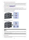
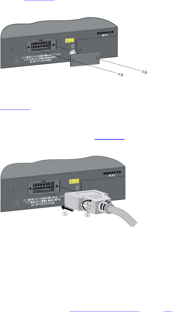
Step2 Loosen the captive screws on the RPS receptacle protective cover and remove the protective cover, as
shown in
Figure 3-13. (If you do not use the +12 VDC RPS interface, install the protective cover.)
Figure 3-13 Connect an RPS power cord (1)
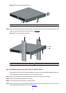
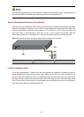
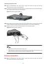
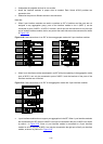
Step3 Keep the upside of the +12 VDC RPS plug on top and plug it in the RPS DC receptacle (see callout 1 in
Figure 3-14). (If you plug it with the upside down, the insertion is not smooth because of the specific
structure design of the RPS DC receptacle and the RPS plug.)
Step4 Use a flat-blade screwdriver to fix the two screws on the RPS plug clockwise to secure the plug to the
RPS DC receptacle (see callout 2 in
Figure 3-14).
Figure 3-14 Connect an RPS power cord (2)
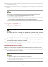
Step5 Connect the other end of the +12 VDC RPS power cord to the external RPS power supply system.
Step6 Check whether the RPS LED on the front panel of the switch is ON. If yes, the power is properly
connected.
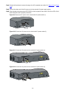
Installing an Interface Module
The Switch 4510G provide two interface module slots on the rear panel. For details about optional
interface modules, refer to
Optional Interface Modules on page 1-9.
The installation and removal of various interface modules are similar. This section describes the
installation and removal of the Dual-Port 10 GE XFP Interface Module (3C17766) for illustration.