


3-13
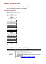
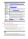
No Task Remarks
2
Install the IRF
members to the
correct position
For detailed installation procedures, see:
z Installing the Switch into a 19-Inch Rack Using Mounting Brackets.
z Mounting the Switch on a Workbench.
3
Connect
grounding
cables and
power cords for
the switches
For details, see:
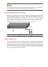
z Connecting the Grounding Cable
z Connecting the Power Cords
4
Power on the
IRF members
—
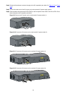
5
Install interface
modules
For details, see Installing an Interface Module.
6
Configure
software for the
IRF members
For details about the IRF function, see IRF Configuration in the System
Volume of the 3Com Switch 4510G Family Configuration Guide.
7
Power off the
switches
—
8
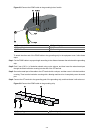
Connect the
cables
Use cables to connect 10 G ports of the interface modules:
z The given XFP ports work with XFP optical transceivers and fibers
z The given SFP+ ports can work with SFP+ optical transceivers and
fibers for long-haul transmission; or they can be directly connected
through dedicated SFP+ cables for short-haul transmission
z The given CX4 ports use dedicated CX4 cables for connection
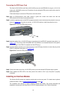
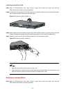
For details about the cable connection, refer to
Installing Dedicated
CX4/SFP+ Cable
.
9
Power on the
switches
Finish establishing an IRF
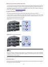
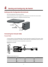
Drawing a Plan for an IRF with Switches
Before implementing an IRF of switches, draw a plan according to actual conditions of the user network
and network devices and take the following points into consideration:
Determine the number of IRF members and the bandwidth
You can determine the number of IRF members and the bandwidth according to the network scale.
z The Switch 4510G support two to four switches in a stack.
z The Switch 4510G support aggregation of the 10 GE ports. You can assign the two 10 GE ports of
an interface module to an aggregation group to expand the bandwidth for the stack.
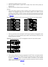
10 GE ports of different interface modules cannot join the same aggregation group in the IRF. Therefore,
1-port XFP interface modules do not support port aggregation in the IRF.