


20 Chapter 1: Introducing the Router 5000 Family
3Com Router 5642
(3C13755)
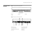
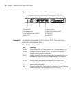
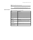
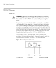
Figure 5 Front view of 3Com Router 5642
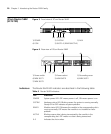
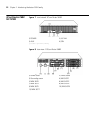
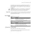
Figure 6 Rear view of 3Com Router 5642
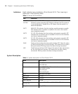
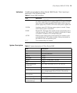
Indicators The Router 5642 LED indicators are described in the following table:
1) POWER 2) SYSTEM 3) AUX
4) CON 5) SLOT0~3 (READY/ACTIVE)
1) Power switch 2) Power socket 3) Grounding screw
4) MIM SLOT1 5) MIM SLOT0 6) MIM SLOT2
7) MIM SLOT3
(2)
(3) (4)
(5)
(1)
{
(1) (2) (3) (4)
(5)
(6)
(7)
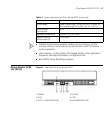
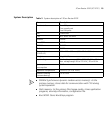
Table 6 Router 5642 Indicators
LED Indication
POWER System power LED: OFF means power is off, ON means power is on.
SYSTEM Hardware status LED: Blinking means the system is running normally.
Steady ON or OFF indicates a system problem.
READY Module status LED: ON means the module in the corresponding slot is
running normally. OFF means the module is not installed or has a
problem.
ACTIVE Blinking means data is being transceived by the module in the
corresponding slot. OFF means no data is being transceived.
0–3 Indicates the slot number.