


34 Chapter 2: Installation
CAUTION: The baud rate should not exceed 64kbps when the V.24 cable
operates in synchronous mode.
■ DTE and DCE
Synchronous serial interface can operate in both DTE and DCE mode. For
two devices connected directly, one should operate in DTE mode, and the
other should operate in DCE mode. The device at the DCE side provides a
synchronous clock and specifies the transmission rate, while the device at
the DTE side accepts the synchronous clock and communicates at the
specified baud rate. Usually, the router serves as a DTE device. To
determine whether the device connected to the router is a DTE or DCE,
please refer to the manual that came with the device. Also the following
table will be helpful in identifying DTE and DCE. Usually, the PC or Router
serves as a DTE device and the Modem, Multiplexer or CSU/DSU serves as
a DCE device.
In general, the asynchronous serial interface is connected to an external
Modem or a Terminal Adapter (TA) to work as the dial-up interface. In
this case, it is unnecessary to determine whether the device is DTE or
DCE, and just choose an appropriate baud rate.
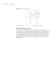
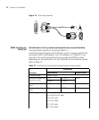
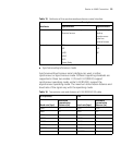
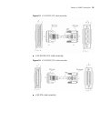
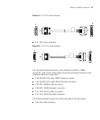
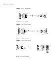
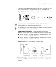
Synchronous/asynchronous serial interface cable The WAN
interface of the router is a DB50 receptacle. Proper connection cable
needs to be selected for the protocol applied. By far, nine types of
synchronous/asynchronous serial interface cables are available. One end
of all the nine types of cables is DB50 connector, the other end (network
end) varies with the cable type, which can be:
■ V.24 (RS232) DTE cable: DB25 (male) connector
■ V.24 (RS232) DCE cable: DB25 (female) connector
■ V.35 DTE cable: 34PIN (male) connector
■ V.35 DCE cable: 34PIN (female) connector
■ X.21 DTE cable: DB15 (male) connector
■ X.21 DCE cable: DB15 (female) connector
The following figures show the cable assembly of all these types:
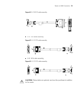
■ V.24 (RS232) DTE cable assembly