Router to WAN Connection 41
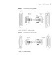
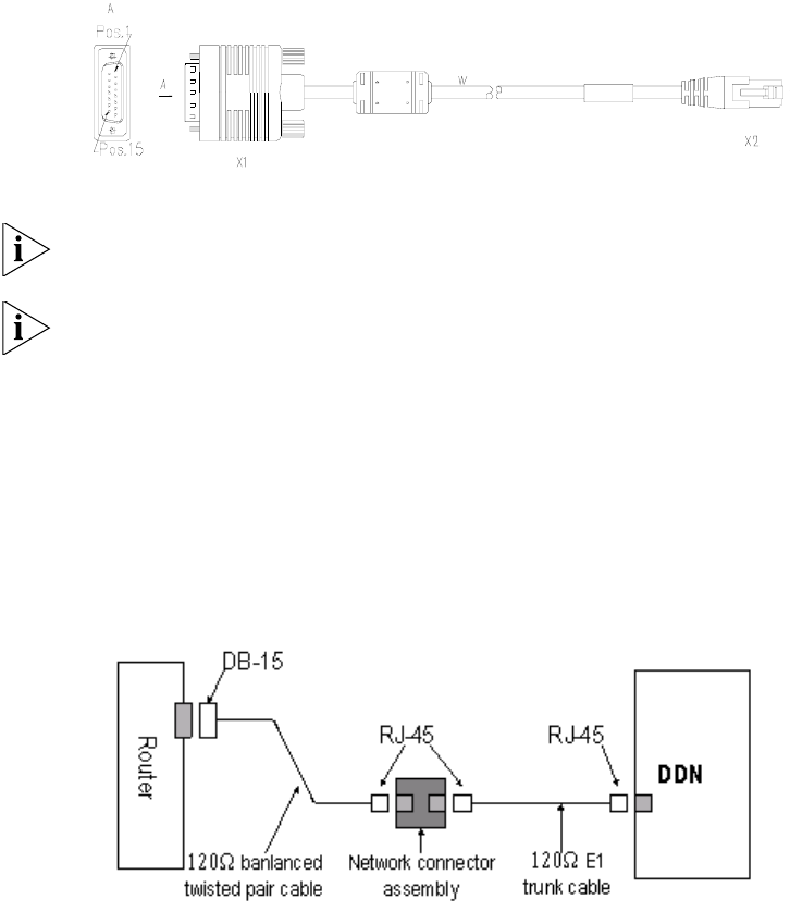
The cable is attached with DB15 (male) connector for the router end, and
with RJ45 connector for the network end. See the following figure:
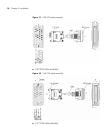
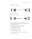
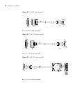
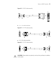
Figure 28 E1 120Ω balanced twisted pair cable
You can also choose to attach both ends with RJ45 connectors, for
extending two 120? balanced twisted pair cables.
E1 interface cable, coax connector assembly, network connector assembly
and 75Ω-120Ω converter all are optional.
Impedance inverter switch Impedance inverter switch is also
available, through which you can choose the interface impedance value.
■ Turn on the switch to change the interface impedance to 75Ω, and
then you need to connect the 75Ω cable.
■ Turn on the switch to change the interface impedance to 120Ω, and
then you need to connect the 120Ω cable.
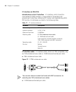
Figure 29 Extending E1 120Ω balanced twisted pair cable
1 Observe the status of the Link LED for the E1 interface. ON means that a
link is present. OFF means that no link is present and you need to check
the line.


