


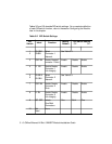

3 - 8 ONline Ethernet 24-Port 10BASE-T Module Installation Guide
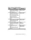
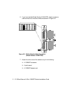
Tables 3-2 and 3-3 describe DIP switch settings. For a complete definition
of each DIP switch function, refer to the section Configuring the Module
later in this chapter.
Table 3-2. DIP Switch Settings
DIP
Switch
Label Function
Factory
Default
DIP Switch Setting
Off On
1
2
CH SEL0
CHSEL1
Select
Connector 1
Network
See Table 3-3.
3 PORT EN Enable/DisableC
onnector 1 Ports
Enable Disable Enable
4 LI EN Enable/Disable
Connector 1
Link Integrity
Enable Disable Enable
5
6
CH SEL 0
CH SEL 1
Select
Connector 2
Network
See Table 3-3.
7 PORT EN Enable/Disable
Connector 2
Ports
Enable Disable Enable
8 LI EN Enable/Disable
Connector 2
Link Integrity
Enable Disable Enable
9 ISO SEP Isolate
One/Both
Connectors
One Both One
10 Not
Used
None