


LEDs 2-3
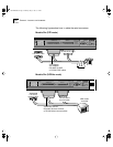
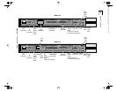
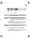
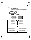
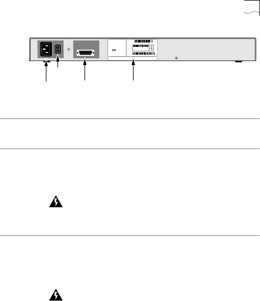
Figure 2-2 Chassis Back Panel
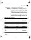
LEDs See “LED Meanings” on page 4-3 for a complete description of the
SuperStack II bridge/router LEDs.
Hardware
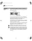
Interrupt Switch
The hardware interrupt switch is located on the left side of the
bridge/router (when facing the front panel). It is recessed into an
opening near the DIP switches. Press the switch with a nonconductive
object, such as a plastic stylus to put the system into the monitor
firmware utility.
WARNING: Use only a nonconductive object such as a plastic stylus to
press the hardware interrupt switch. Do not use the tip of a pencil.
Graphite particles from the pencil may cause you to receive an electric
shock and damage components on the motherboard.
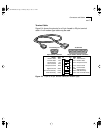
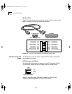
Connectors and
Cables
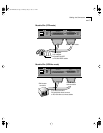
This section describes each connector on the bridge/router.
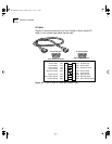
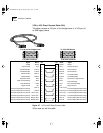
Console Cables You can connect a PC running a terminal emulation program, a
terminal, or a modem to the Console port on the SuperStack II
bridge/router.
WARNING: To eliminate cable noise emission in excess of FCC Part 15,
Subpart J, and EN55022 B, this device cable should be shielded and
have connectors with metallic backshells.
Power
receptacle
On/off
switch
MODEL: ESPL-310
REMOTE OFFICE
NETBUILDER
222
S/N:
1SC05427
100-240VAC, 50/60HZ, 1.0-0.5A
250V, F2A
8.3
FOR CONTINUED PROTECTION
AGAINST FIRE HAZARD
REPLACE FUSE ONY WITH
SAME TYPE AND RATING
NTWK
ADDR:
3COM CORP.
SANTA CLARA, CA. MADE IN USA
080002 04BA1E LAN
04BA1F
04BA20
04BA21
WAN-A
WAN-B
WAN-C
20-0261-000
07/31/95
RPS
connector
Product
information label
SS2TRHWBook Page 3 Monday, May 5, 1997 3:11 PM