


2-6 CHAPTER 2: OVERVIEW
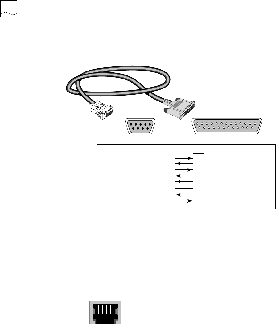
Modem Cable
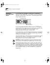
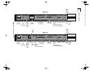
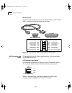
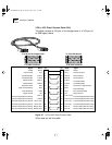
Figure 2-5 shows the pinouts for a 9-pin female to 25-pin male modem
cable. A straight-through-type cable may be used.
Figure 2-5 9-pin to 25-pin Modem Cable (Straight-Through-Type)
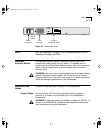
LAN Connectors and
Cables
The bridge/router has two token ring connectors. Only one connector
can be used at one time.
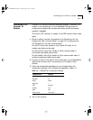
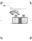
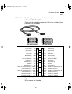
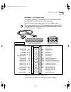
UTP Connector and Cable
The following figure shows the pinouts of the UTP connector (RJ-45).
The connector bodies connect the cable shield to chassis ground.
Table 2-2 lists cable types, multistation access units (MAUs), and
emissions classes compatible with the UTP connector.
1 2 3 4 5 6 7 8 9 10 11 12 13
14 15 16 17 18 19 20 21 22 23 24 25
5 4 3 2 1
9 8 7 6
25-pin male connector
9-pin female connector
To Console port
To modem
Name Abbr Pin Pin Abbr Name
3
2
4
8
5
7
6
20
Receive Data
Transmit Data
Request to Send
Carrier Detect
Clear to Send
Signal Ground
Data Set Ready
Data Terminal Ready
RxD
TxD
RTS
CD
CTS
GND
DSR
DTR
TxD
RxD
RTS
CD
CTS
GND
DSR
DTR
Transmit Data
Receive Data
Request to Send
Carrier Detect
Clear to Send
Signal Ground
Data Set Ready
Data Terminal Ready
3
2
7
1
8
5
6
4
12345 786
UTP
3 TX
4 RX
5 RX
6 TX
RJ-45 female (shielded)
SS2TRHWBook Page 6 Monday, May 5, 1997 3:11 PM