


16 CHAPTER 1: PRODUCT OVERVIEW
Role and function
The MBUS system is powered by 5 V from the MBUS on the fabric. The 5 V power
on the two fabrics are redundant to each other.
Each MBUS module is attached to the MBUS, which contains two control lines:
MBUS0 and MBUS1.
Each card has an independent MBUS module, those on the fabrics are primary
MBUS modules, and those on application modules are secondary MBUS modules.
When the fabrics operate in redundancy mode, the MBUS module on the active
fabric is the active module, and the one on the standby fabric is the standby
module.
The MBUS uses a controller area network (CAN) bus as its control bus, that uses
the 1:1 hot backup and transfers control information at 1 Mbps.
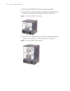
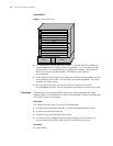
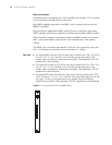
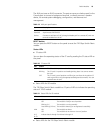
Fan Tray ■ The Switch 8807 uses one 25 W fan tray, which contains four 120 x 120 x 25.4
mm (4.7 x 4.7 x 1.0 in.) axial fan units. The fans can be governed in two
modes: fabric-controlled or temperature-controlled. They operate at -48 VDC
supplied from the backplane.
■ The Switch 8810 uses one 35 W fan tray, which contains six 120 x 120 x 25.4
mm (4.7 x 4.7 x 1.0 in.) axial fan units. The fans can be governed in two
modes: fabric-controlled or temperature-controlled. They operate at -48 VDC
supplied from the backplane.
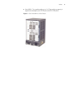
■ The Switch 8814 uses two 25 W fan trays, each of which contains four 120 x
120 x 25.4 mm (4.7 x 4.7 x 1.0 in.) axial fan units (and totally eight for the two
fan trays). The fans can be governed in two modes: fabric-controlled or
temperature-controlled. They operate at -48 VDC supplied from the backplane.
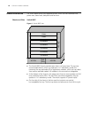
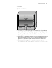
Figure 9 Fan tray panel of the Switch 8800 Family