


Mounting the Switch in User-Supplied Cabinet 55
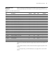
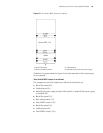
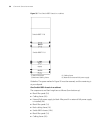
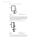
Figure 34 One Switch 8807 chassis in a cabinet
Guideline: The space marked in Figure 34 must be reserved, and the remaining is
at your disposal.
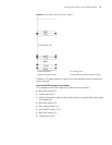
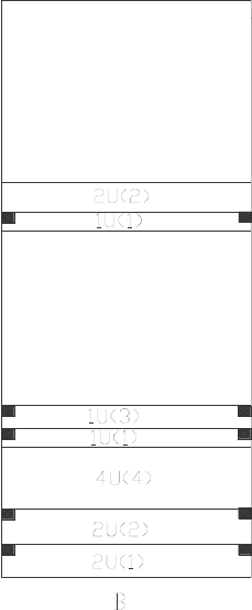
Two Switch 8807 chassis in a cabinet
The components and their height are as follows (from bottom up):
■ Blank filler panel (2U)
■ Cabling frame (2U)
■ External PoE power supply (or blank filler panel if no external PoE power supply
is installed) (4U)
■ Blank filler panel (1U)
■ Back cabling frame (1U)
■ Switch 8807 chassis (11U)
■ Blank filler panel (1U)
■ Cabling frame (2U)
■ Switch 8807 chassis (11U)
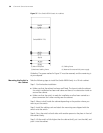
(1) Blank filler panel (2) Cabling frame
(3) Backward cabling frame (4) Reserved for external PoE power supply
Switch 8807 11U