


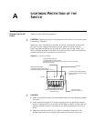


98 CHAPTER A: LIGHTNING PROTECTION OF THE SWITCH
connected in right direction. When the red LED is on, use a multimeter to
examine the polarity at the arrester’s power socket. If it is same as that of the
power socket in the equipment room, it means that the arrester is not well
grounded. If it is adverse to that of the power socket in the equipment room, it
means that the arrester’s power socket is set to the reverse polarity. In this case,
you should open the arrester’s power socket and correct the polarity. After
that, if the red LED still alarms, it means that the arrester is still not well
grounded.
Installing a Lightning
Arrester for the
Network Port
n
A network port lightning arrester is specifically designed for an 10/100M electrical
interface (an RJ-45 connector in this case) Ethernet port.
Make sure, when connecting an outdoor AC power cord directly to the switch,
that you connect a lightning arrester to the AC power (a socket strip with
lightning protection) before you plug the AC power cord into the switch. This
helps to prevent damage in the event of a lightning strike. Install your lightening
arrester according to its manufacturer’s instructions.
Required tools
■ Phillips screwdriver or flat-module screwdriver
■ Multimeter
■ Tilted wire cutter
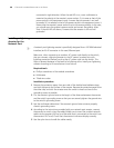
Installation procedure
1 Remove the protection paper from one side of the double-faced adhesive tape,
and stick the tape to the surface of the arrester. Remove the protection paper from
the other side, and stick the arrester onto the switch’s chassis as close to the
grounding screw as possible.
2 Cut the arrester’s ground wire to the length of the distance between the arrester
and the switch’s grounding screw so that you can securely tighten the ground wire
to the switch’s grounding screw.
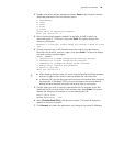
3 Use the multimeter determine if the arrester’s ground wire connects properly
chassis’s grounding screw.
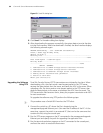
4 According to the instructions provided with your network port arrester, connect
the arrester to switch using the cables (Make sure to insert the outdoor network
cable into the arrester‘s IN end, and the cable that is connected to the switch into
the arrester’s OUT end). Check that the arrester’s indicators display correctly.
5 Use the nylon ties to bundle the cables neatly.