


Hardware Maintenance 85
Installing a Module
1 Wear the ESD-preventive wrist strap and unscrew the mounting screws fixing the
blank filter panel in the slot where you want to install the module, and remove the
blank filler panel.
2 Hold the ejector levers of the card with both hands and pull them outward, align
the card with the guides in the chassis, and slide it gently into the slot until its
positioning pin touches the positioning hole in the chassis.
3 Pull the ejector levers inward to lock the positioning pin of the card into the
positioning hole in the chassis.
4 Fasten the screws to fix the card.
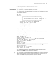
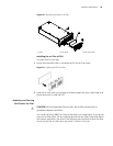
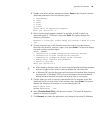
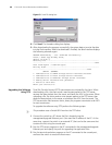
Figure 61 Installing a Module
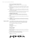
Replacing the Fan Tray
c
CAUTION: To avoid bodily injury, do not touch exposed wires, terminals, or the
switch parts where a dangerous voltage warning label is indicated.
Required tools
■ ESD-preventive wrist strap
■ Screwdriver
Replacing the Fan Tray
To replace the fan tray:
1 Wear the ESD-preventive wrist strap.
2 Remove the screws from both sides of the fan tray.
3 Pull the fan tray out with one hand on the top and the other hand around the
handle of the fan tray to separate the fan tray positioning pin from the backplane.
c
CAUTION: When you replace the fan tray of an operating switch, pull the fan tray
out from the chassis only after the fans stop rotating. In this case, there is still the
possibility that fans are still rotating. Therefore do not put your hand into the fan
tray to avoid bodily injury.
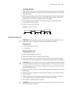
4 Gently pull the fan tray out of the slot along the guides and place fan tray into the
packing bag.
5 Hold the fan tray’s handle with one hand and its bottom with the other and pull
them outward.
6 Align the fan tray with the guides in the chassis and slide it gently into the slot
until its positioning pin touches the positioning hole in the chassis.
7 Insert screws on both sides of the fan tray.
c
CAUTION: Install a new fan tray soon after removing the old one to ensure that
the switch operates normally.