


Hardware Description 17
Back Panel Connector
Description
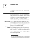
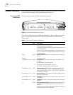
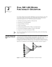
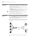
The back panel contains the connectors illustrated in Figure 6.
Figure 6 Dual 56K LAN Modem Back Panel
From left to right, the back panel consists of the following:
■ Power: Connect the power module cable to this port.
■ RESET: Press this button to re-initialize or factory re-set the unit (refer to
Chapter 10 for instructions).
■ LAN 1, 2, 3, and 4: Connect up to four computers (or a combination of
computers and an external hub), to these four 10BASE-T Ethernet ports.
■ LINE 1: Connect one of the provided RJ-11 analog cables from the wall outlet
to this port.
■ PHONE 1: Connect an external analog device, such as a telephone or fax
machine, to this port.
■ LINE 2: Connect the second RJ-11 analog cable from the wall outlet to this
port.
■ PHONE 2: Connect an additional external analog device, such as a telephone
or fax machine, to this port.
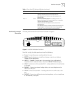
COLL Amber Ethernet Collision Status. Flashes amber when some
collisions are taking place on the Ethernet LAN.
Off indicates that no collisions are taking place on the
Ethernet LAN.
Ports 1-4 Green Ethernet LAN Port Status. On indicates that the unit
detects the Ethernet link integrity signal from an attached
computer and operation is normal.
Flashes when the LAN Modem receives data on the
associated port.
Off indicates that the unit does not detect the Ethernet link
integrity signal. The Ethernet cable may not be properly
connected or the cable may be the wrong polarity.
Table 4 Front Panel LED Indicator Definitions (continued)
LED Color Description
10-30V DC
2A MAX
RESET
1
3
2
4
LAN
LINE 1 PHONE 1 LINE 2 PHONE 2