


21
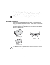
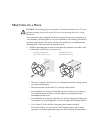
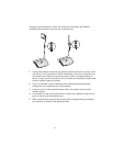
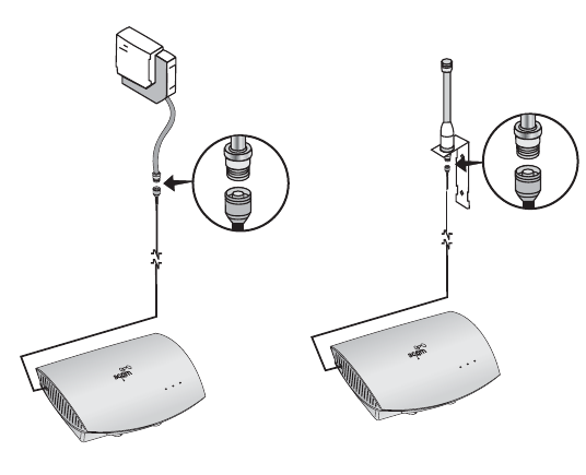
Antennas can be connected to either side of the access point after the standard
detachable antennas have been removed, as shown below.
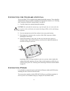
1 Position the antenna so that there are minimal obstacles between it and any client
with which it will communicate. While maintaining a direct line of sight between
the antenna and a client is not strictly necessary, such an arrangement helps to
ensure a strong signal. Ensure that access is available for routing the antenna cable
from the antenna to the access point.
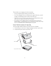
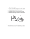
2 If they are installed, remove both arms of the standard detachable antennas,
making sure not to handle the tips of the antennas.
3 Connect one end of the optional antenna cable to the antenna and secure the
antenna in place.
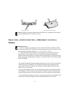
4 Connect the free end of the antenna cable to either side connection on the access
point, as shown in the illustration above.
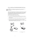
5 Make certain that the antennas and antenna masts are appropriately grounded to
prevent injury or damage from lightning strikes.
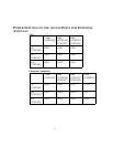
Radio
Etherne
t
Power
Ra
dio
Eth
ernet
Power