


19
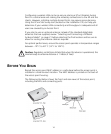
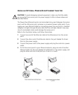
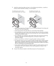
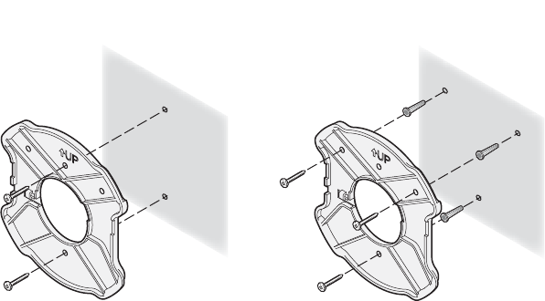
1 Install the mounting plate as shown in the following illustration, on either a
stud (or other hard wall surface), or onto drywall.
Allow for a clearance of at least 25 cm (10 Inches) between the ceiling and
the top of the mounting plate.
Orient the bracket with the letter “B” at the top of the bracket.
For installation on a wall stud, install the top screw into the stud, as shown
at left in the illustration, and then vertically align the mounting plate before
installing the bottom screw.
For installation on to drywall, mark three screw holes using the mounting
plate as a template for vertical alignment, as shown at right in the
illustration above.
Use a 5-mm (3/16-in.) drill bit if using the plastic anchors provided.
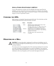
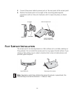
For drywall mounts, you can route the cable through either a side or center
opening for a seamless appearance using one of the methods illustrated
below. Alternatively, you can simply attach the Ethernet cable to the side of
the unit, allowing it to trail along the wall.
If you have routed the Ethernet cable through the center opening, secure
the cable on the hook located on the mounting plate as shown in the
illustration below.
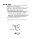
2 Connect the Ethernet cable to the Ethernet port on the access point.
If installing into drywall, use
3 plastic anchors and 3 screws.
If installing into a stud or other
secure vertical surface, use 2 screws.