


22
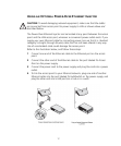
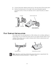
1 Position the antenna so that there are minimal obstacles between it and any
client with which it will communicate. While maintaining a direct line of sight
between the antenna and a client is not strictly necessary, such an
arrangement helps to ensure a strong signal. Ensure that access is available
for routing the antenna cable from the antenna to the access point.
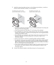
2 If they are installed, remove both arms of the standard detachable antenna,
making sure not to handle the tips of the antenna.
3 Connect one end of the optional antenna cable to the antenna and secure
the antenna in place.
4 Connect the free end of the antenna cable to the right-hand side connection
on the access point, as shown in the illustration above.
5 Make certain that the antennas and antenna masts are appropriately
grounded to prevent injury or damage from lightning strikes. Proper
grounding for outdoor installations may require the purchase of a third-party
lightning arrestor.
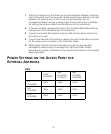
POWER SETTINGS ON THE ACCESS POINT FOR
EXTERNAL ANTENNAS
USA
2.5dBi
(3CWE492)
4dBi
(3CWE490,
3CWE497)
8dBi
(3CWE491,
3CWE498)
6 ft
(3CWE580)
100% 100% 100%
20ft
(3CWE581)
100% 100% 100%
50 ft
(3CWE582)
100% 100% 100%