


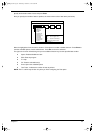
Chapter 3 39
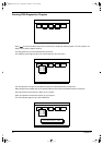
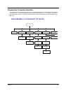
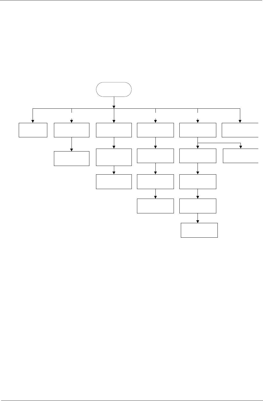
Disassembly Procedure Flowchart
The flowchart on the succeeding page gives you a graphic representation on the entire disassembly sequence
and instructs you on the components that need to be removed during servicing. For example, if you want to
remove the system board, you must first remove the keyboard, then disassemble the inside assembly frame in
that order.
Start
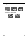
Battery Modem Cover
HDD Module FDD Connector
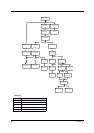
DISASSEMBLY FLOWCHART OF TM730
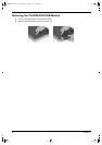
DIMM
Modem Board
Ax1
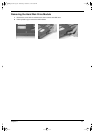
CD-ROM/DVD
ROM Module
HDD Cover
Bx1
CD-ROM/
DVD-ROM
FPC Cable
HDD Connector
CD-ROM/
DVD-ROM
Drive
HDD
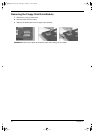
DIMM Cover
FDD Module
FDD Bracket
Ax1
Main Unit
(see next page)
FDD