


AcerPower 2100 User’s Guide2-4
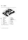
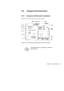
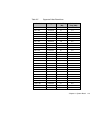
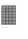
2.2 Layout
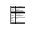
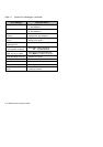
Figure 2-1 shows the locations of the major components on the system board.
1 RJ-45 LAN port 15 DIMM sockets
2 PS/2 keyboard port 16 CPU connector
3 PS/2 mouse port 17 Voltage regulators
4 Serial port 18 AIO board connector
5 USB port
6 Riser card slot
19 Sound Blaster compatible audio
controller
7 Ultra I/O controller 20 FDD connector
8 Parallel port 21 IDE1 connector
9 VGA port 22 IDE2 connector
10 System BIOS chipset 23 Power connector
11 3-D AGP video controller 24 CD-in connector
12 Video memory 25 Battery
13 PCI/AGP/memory controller 26 PCI IDE controller
14 Buzzer 27 Ethernet controller
Figure 2-1 System Board Layout
1
2
3
4
5
8
9
27
10
12
13
15
14
7
26
23
6
16
17
19
11
18
22
21
20
25
24