


User Guide for AIR-104/AIR-204 2-3
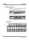
of operation for LAN port 1 is located along the right edge of the router case (see Figure
2-2). Locate the switch and set it to NORMAL mode. Then use an RJ-45 to RJ-45 cable
(not supplied) to connect LAN port 1 to your PC’s Ethernet interface.
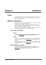
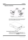
Connecting PC’s to the router via a hub or switch
If your network contains more than four PC’s, you will need first to connect the majority of
your PC’s to each other with an external hub or switch, and then connect that hub or
switch to LAN port 1 on the AIR-104/204 (see Figure 2-1). In this configuration, LAN
ports 2,3, and 4 on the AIR-104/204 can still directly connect to PC’s as described
above.
Step 1 Connect your PC’s to the external hub or switch. Consult the manufacturer’s
instructions for direction.
Step 2 Connect a node port (one that would normally be used to connect a PC
directly) on the external hub or switch to LAN port 1 on the AIR-104/204,
using an RJ-45 to RJ-45 cable (not supplied). Locate the switch that controls
the mode of operation for LAN port 1 on the AIR-104/204, and set it to
UPLINK (this switch is located along the right edge of the router case). See
Figure 2-2. If you are using a special uplink port on the external hub or switch
to connect to LAN port 1 on the AIR-104/204 , then set the mode of
operation for LAN port 1 on the AIR-104/204 to
NORMAL.
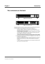
Console connection
You may directly connect a console PC running terminal emulator such as HyperTerminal
to the AIR-104/204. To make the connection, use the special RJ-45 to DB-9 cable (
Null
Modem Cable
) supplied in the package. One end of the cable is a 9-pin DB-9 SCSI
cable; plug this into either the
COM1
or
COM2
port of the console PC and turn the
screws until finger-tight to seat. The other end of the connector cable is a standard RJ-45
network-cable plug; plug this into the
CONSOLE
jack on the AIR-104/204.
External phone line
You may connect either a telephone handset or a fax machine to the AIR-204 (not the
AIR-104) via the
PHONE
jack. Use an RJ-11 to RJ-11 cable (only one is supplied) to
make the connection.
Chapter 2 Installation