


Appendix A: Specifications
MM701F User Manual 73
Connector Pinouts
The following sections provide the pinout information for the various modem connectors.
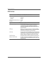
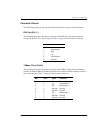
DSL Port (RJ-11)
The following table shows the signal on each pin of the DSL port. The connector for this
interface is an RJ-11. See “Connecting the Cables” on page 5 for the location of this port.
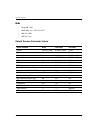
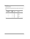
10Base-T Port (RJ-45)
The following table shows the signal on each pin of the 10Base-T port connector when the
switch is in either the MDI or the MDI-X position. The connector for this interface is an RJ-45.
See “Connecting the Cables” on page 5 for the location of this port.
Pin Signal
1 Not used
2 No connection
3 Ring
4 Tip
5 No connection
6 Not used
MDI MDI-X Signal Description
1 3 TX+ Transmit Data (+)
2 6 TX- Transmit Data (-)
3 1 RD+ Receive Data (+)
4 4 Not used Not used
5 5 Not used Not used
6 2 RD- Receive Data (-)
7 7 Not used Not used
8 8 Not used Not used