


ADCP-61-814 • Issue 1 • April 1999
Page 7
© 1999, ADC Telecommunications, Inc.
Note:
PWR-AVIS units configured with the single powering option can be upgraded to
redundant power by ordering an additional power supply module (PWR-AVIS-PSC).
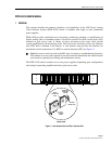
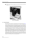
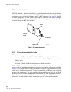
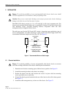
The PWR-AVIS provides two sets of screw terminal contacts (see Figure 8) at the rear of the
chassis for connecting to a -48V office power supply. Alternately, a 110-48V (PWR-AVIS-
110-ST) converter (purchased separately) can be attached to either set of contacts.
2.2.2 Alarms
As shown in Figure 8, PWR-AVIS incorporates two pair of screw terminal alarm contacts
(PS1-A and B, and PS2-A and B) located at the rear of the chassis. The contacts may be used
as an interface to any existing customer-supplied alarm system. Both A and B contacts
perform the same function and can be used with two independent types of warning signals,
either audible or visual. If the power supply voltage drops below a normal operating threshold
of 3.5VDC, failure is detected and alarm(s) are triggered. The alarm contacts are normally
open and will close when a failure occurs.
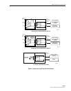
2.2.3 Single/Dual Powering and Alarms
When PWR-AVIS is configured with a single power supply, only the PS1 alarms should be
used. If the power supply fails in this configuration continuity will occur between the PS1
alarm terminals and all RIUs will lose power.
When PWR-AVIS is configured with two power supplies, it normally operates using the
primary power supply. If the primary power supply fails, its alarms will activate and the
secondary power supply will seamlessly begin to provide power to the chassis. When the
primary power supply begins to operate properly (after replacement or maintenance), its alarm
will deactivate and it will seamlessly override the secondary power supply. In all cases
(except where both power supplies fail) all RIUs will continue to be supplied with power.
OUT
TEST
AVIS
IN
12247-B
SPARE
SPARE
–48V (1)
RET (1)
–48V (2)
RET (2)
PS1 ALM A
PS1 ALM B
PS2 ALM A
PS2 ALM B
CLASS 2
Figure 8. Power and Alarm Contacts