


ADCP-61-814 • Issue 1 • April 1999
Page 15
© 1999, ADC Telecommunications, Inc.
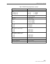
TEST
16
15
14
13
12
11
10
9
8
7
6
5
4
3
2
1
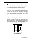
AVIS-16
SIGNAL OUTPUT
SIGNAL INPUT
CHASSIS GROUND
12250-B
SPARE
SPARE
–48V (1)
RET (1)
–48V (2)
RET (2)
PS1 ALM A
PS1 ALM B
PS2 ALM A
PS2 ALM B
CLASS 2
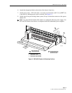
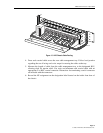
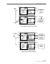
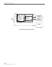
Figure 15. AVIS Chassis Cable Routing
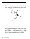
4. Dress each coaxial cable across the rear cable management tray. Follow local practice
regarding the use of lacing cord or tie wraps for securing the cables to the tray.
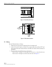
5. Measure the length of cable from the cable management tray to the designated RIU,
allowing slack for tension relief. Cut, strip, and terminate each coaxial cable with an
appropriate F or BNC coaxial connector. Instructions for terminating coaxial connectors
are included with the connectors.
6. Record the NE assignment on the designation label located on the inside front door of
the chassis.