


ADCP-61-814 • Issue 1 • April 1999
Page 12
© 1999, ADC Telecommunications, Inc.
3 INSTALLATION
Danger
:
To avoid the possibility of severe and potentially fatal electric shock, never install
electrical equipment in a wet location or during a lightning storm.
Caution
:
Always wear an anti-static discharge wrist strap to prevent static electric discharge
damage to the Jack Access Card electronic circuitry.
The PWR-AVIS chassis mounts in a 19- or 23-inch (48.3 or 58.4 cm) equipment rack. The
chassis can be mounted flush with the rack, or extended 2.0 inches (5.0 cm) out in front of the
rack. Mounting screws, reversible mounting brackets, designation labels and cable
management tray are shipped with the chassis.
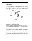
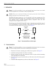
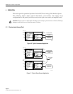
The cable type used for the NE IN and OUT circuits is dependent upon application, type of
service and equipment. All cables should be 75 ohm coaxial with tinned copper shield. The
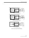
recommended maximum lengths are from NE to NE. See Figure 11.
0 TO 300 Mhz IF/RF Circuits
Cable Type – HEC-2
0 TO 6 Mhz Video Circuits
Cable Type – 734S1
100 Feet (30.5 meters)
200 Feet (61.0 meters)
N
E
N
E
IN OUT
AVIS EQUIPMENT
6410-A
Figure 11. Recommended Maximum Cable Lengths
3.1 Chassis Installation
Danger
: To avoid the possibility of severe and potentially fatal electric shock, use extreme
care when working at the back of the chassis with the power terminations.
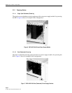
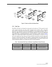
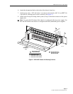
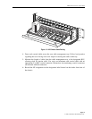
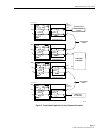
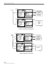
1.Determine rack location, mounting space width and recess position. See Figure 12.
2.Attach the mounting brackets to the chassis accordingly.
3.Position the chassis into the rack location and secure it in place with four mounting
screws (provided), two on each side.
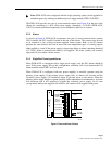
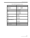
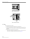
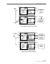
4.Connect the chassis ground terminal at the rear of the chassis to the office frame ground.
See Figure 13.
5.Attach the cable management tray to the rear of the chassis. See Figure 12.