


ADCP-61-814 • Issue 1 • April 1999
Page 9
© 1999, ADC Telecommunications, Inc.
6409-B
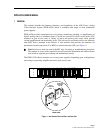
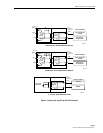
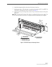
REAR
INTERFACE
UNIT
JACK
ACCESS
CARD
M
O
I
JACK
ACCESS
CARD
AMPLIFIER
CARD
MON
OUT
IN
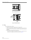
REAR
INTERFACE
UNIT
M
O
I
BB
REAR
INTERFACE
UNIT
MON
OUT
IN
BB
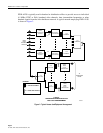
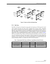
Figure 10. Passive and Active Jack Access Cards
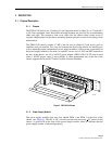
2.2.6 Cable Type
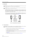
The PWR-AVIS jacks are designed to accept patch cords made up of 735A type mini coaxial
cable equipped with little coax plugs (LCP). Equipment (IN and OUT) cable is dependent
upon service or bandwidth of the associated equipment. Video equipment requires 734S1 or
equivalent cable, equipment operating at intermediate frequencies (IF) and radio frequencies
(RF) require HEC-2 or equivalent type cable. All cables should be 75-ohm coaxial with tinned
copper shield. The recommended maximum length of cable between NEs is shown in Table 1.
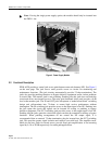
Cables are available with F or BNC connectors factory pre-terminated on one end and a stub
end on the opposite end. The stub end can then be field connectorized using the appropriate
connector to fit the NE Interface. This method of cabling provides exact length cables and
minimizes storage congestion. If the use of pre-terminated cables is not desired, connector kits
with installation procedures are available from ADC for field termination.
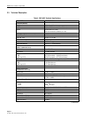
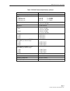
Table 1. Recommended Cable Type and Maximum Length Between Network Elements
CIRCUIT USE CABLE TYPE BANDWIDTH MAX. CABLE LENGTH
Intermediate Frequencies HEC-2 or equivalent 0–300 MHz 200 feet (61.0 meter)
Radio Frequencies HEC-2 or equivalent 0–300 MHz 200 feet (61.0 meter)
Baseband Video 734S1 or equivalent 0–6 MHz 200 feet (61.0 meter)