


ADCP-61-814 • Issue 1 • April 1999
Page 3
© 1999, ADC Telecommunications, Inc.
2 DESCRIPTION
2.1 Physical Description
2.1.1 Chassis
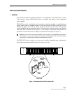
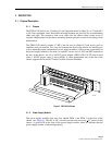
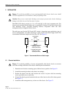
The PWR-AVIS chassis are 3.5 inches (8.9 cm) high and mount in either 19- or 23-inch (48.3
or 58.4 cm) equipment racks. Reversible mounting brackets are provided for accommodating
either rack type. The protective front cover slides into the chassis when circuit access is
required. Hinged plates on the chassis mounting brackets provide an area for recording circuit
identification.
The PWR-AVIS chassis contains 17 RIUs (one for test) in which LCJ jack access cards or
amplifier cards are installed. Two slots are located at the front of the chassis for installing one
or two (depending upon configuration) power supply module(s). Office power connections for
the power supply module(s) are made, as required, via two sets of -48V and RET terminals at
the rear of the chassis. An AC to -48VDC power adapter (PWR-AVIS-110-ST) may be used
when a -48VDC power source is not available. A cable management tray at the rear of the
chassis supports the IN and OUT cables from the Network Elements.
16
1
14
1
1
11
1
9
8
6
4
1
AI-16
IA P
IA IP
CAI D
12249-B
PA
PA
48 1
1
48
P1 A A
P1 A
P A A
P A
CA
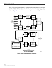
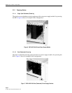
Figure 3. PWR-AVIS Chassis
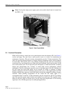
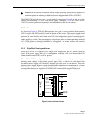
2.1.2 Power Supply Module
The power supply modules slide into slots labeled PWR 1 and PWR 2 at the front of the
chassis (see Figure 4). This DC to DC converter provides the necessary +
5V power for the
chassis. A green LED at the front of the power supply module, when lit, indicates that the
power supply module is functioning properly.