


ADCP-61-814 • Issue 1 • April 1999
Page 14
© 1999, ADC Telecommunications, Inc.
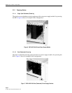
OUT
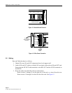
CHASSIS GROUND
1234
IN
6967-B
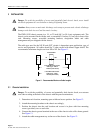
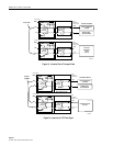
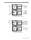
Figure 13. Chassis Ground Terminal
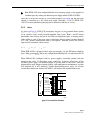
OUT
TEST
AVIS
IN
12248-B
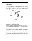
SPARE
SPARE
–48V (1)
RET (1)
–48V (2)
RET (2)
PS1 ALM A
PS1 ALM B
PS2 ALM A
PS2 ALM B
CLASS 2
TO OFFICE
–48V FUSE
PANEL
TO 110 VAC TO
–48VDC CONVERTER
(OPTIONAL)
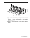
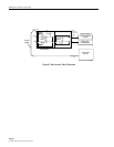
Figure 14. Office Power Connection
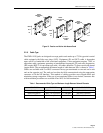
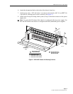
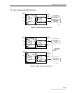
3.2 Cabling
Run and Cable the chassis as follows:
1.Obtain NE circuit IN and OUT assignments from local support staff.
2.Label all IN and OUT cables to identify NE associated with each card IN and OUT jack.
Ensure that the NE OUT cable terminates to the RIU OUT and the NE IN terminates to
the RIU IN.
3.Route the cables from the NE to the rear of the chassis.
Route circuits 1 through 10 on the right side of the rack, as viewed from the rear.
Route circuits 11 through 16 on the left side of the rack. See Figure 15.