


ADCP-61-814 • Issue 1 • April 1999
Page 4
© 1999, ADC Telecommunications, Inc.
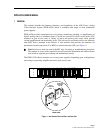
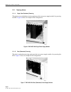
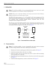
Note:
If using the single power supply option, the module should only be inserted into
the PWR 1 slot.
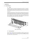
Figure 4. Power Supply Module
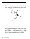
2.2 Functional Description
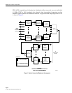
PWR-AVIS provides a central jack access point between network elements (NE). See Figure 5
on the next page. The jack access cards provide access to circuits for monitoring and
maintenance functions. (The jack circuitry automatically provides 75-ohm termination.) The
jacks also provide patching functions to bypass defective equipment and/or isolate problems
in circuit links. The monitor jack is non-switching. Patching into this jack does not break the
circuit and allows non-intrusive access. The unity gain (baseband video) card provides a 0 dB
level at the monitor jack. The IN and OUT jacks incorporate a “make before break” switching
design and self-terminate into 75-ohms to ensure high service performance without
interruption. The IN switching jack provides access to the input signal of an NE. Patching into
the jack opens the circuit and signals can be inserted for testing or patching to bypass
defective equipment. The OUT switching jack provides access to the output signal of an NE.
Patching into the jacks opens the circuit and signals can then be extended for testing or bypass
functions. When patching arrangements do not extend the NE output signal, it is
recommended that an external 75-ohm termination plug be inserted into the OUT switching
jack. This provides greater signal isolation and reduces cross-talk level. The amplifier cards,
which do not have jacks for circuit access, provide fixed gain amplification of an incoming
signal by 0, 10 or 20 dB respectively for return path applications.